Copyright © Neoway Technology Co., Ltd
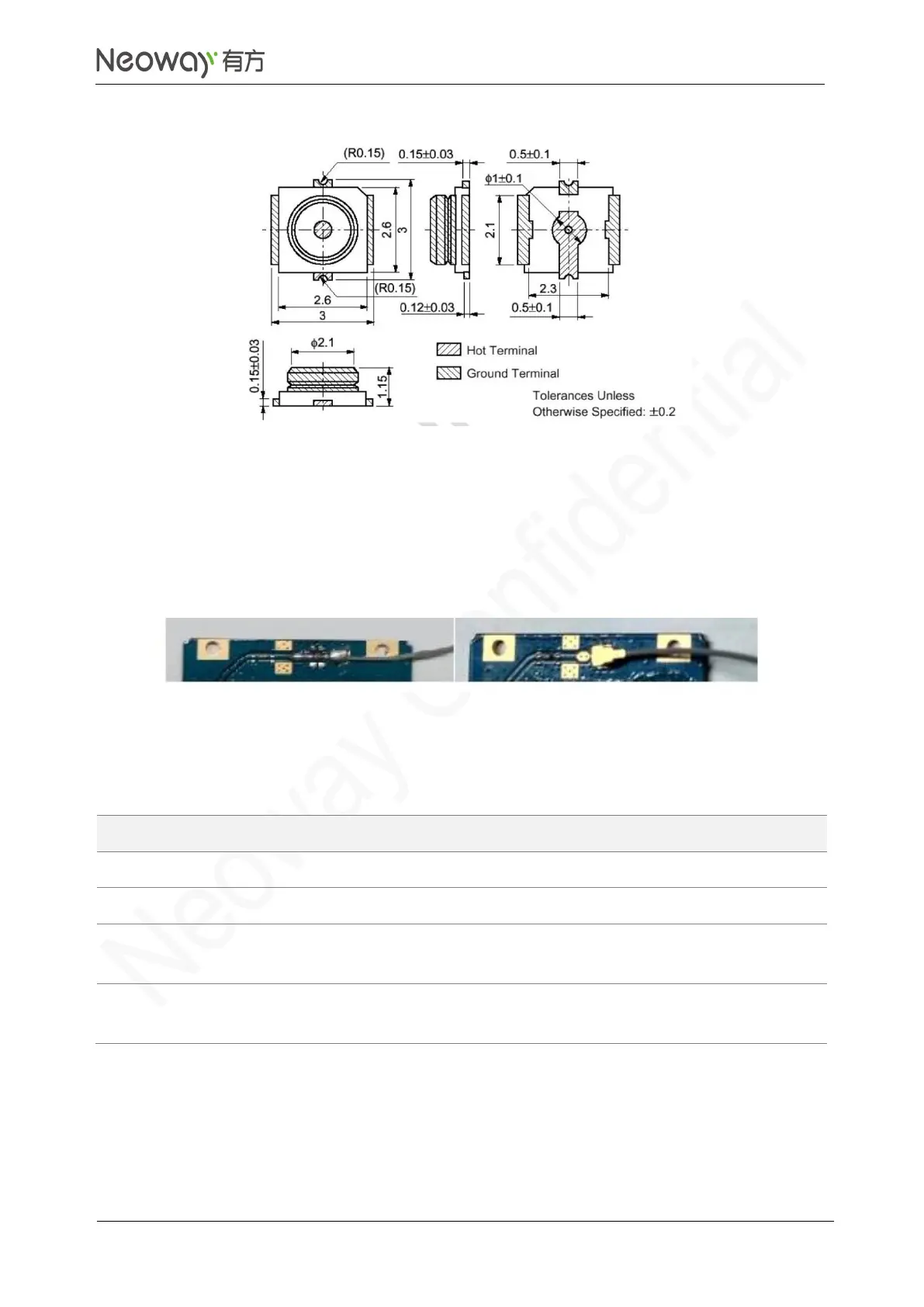
Figure 3-54 Specifications of MM9329-2700RA1
⚫
Soldering
RF wire can also be soldered to connect to the module. Ensure sufficient soldering in case of
damage that lowers RF performance.
Figure 3-55 shows the two types of connections.
Figure 3-55 RF connections
3.6 GPIO
Do not pull this pin high before
the module is started.
Do not pull this pin high before
the module is started.
N75 provides 4 GPIO pins, two among which support interrupt. Do not connect GPIO_78 or GPIO_79
to the power supply through a pull-up resistor before the module is started. Otherwise, the module will
enter download mode forcibly once detecting high level or current input at this pin during startup.