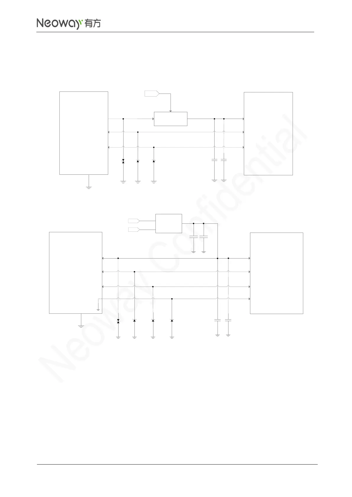
The module can be used as USB Device. It is an option for customers. The recommended USB circuit
is shown in Figure 3-13.
Figure 3-13 USB connection
Schematic Guidelines
⚫
Connect a 1μF and a 22pF filter capacitors in parallel to the USB_VBUS pin. An ESD component
is required for the USB_VBUS line.
⚫
The junction capacitance of the ESD protection diodes for USB_DP and USB_DM should be
lower than 1pF if possible.
⚫
To enter sleep mode, shut down USB_VBUS. Add a switch to USB_VBUS to control it by MCU.
See Figure 3-14. For the switch circuit, see Figure 3-3.