scenarios wherein only one passive or active antenna is used.
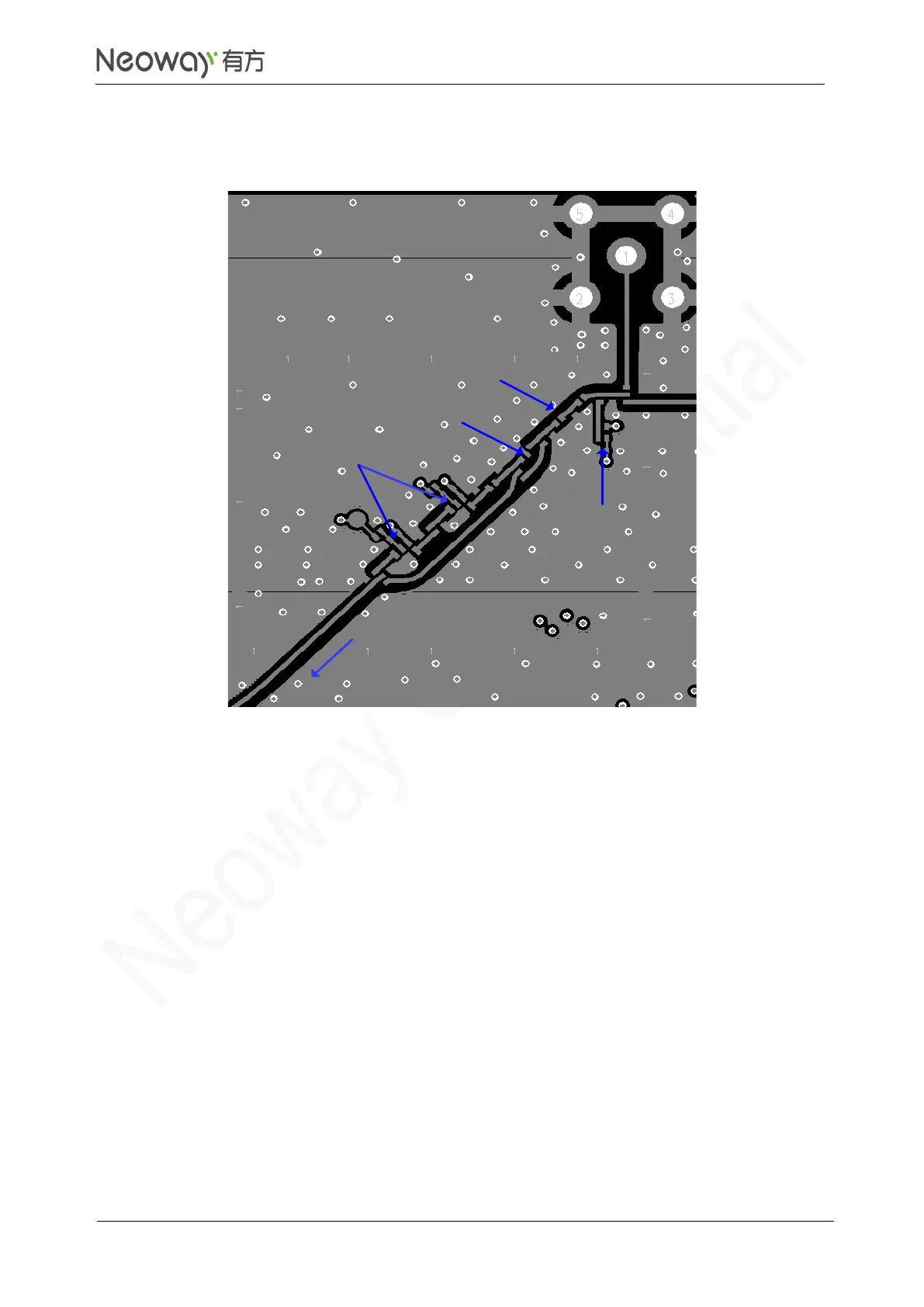
Figure 3-53 Reference layout of GNSS antenna traces
3.5.3 Antenna Assembling
Antenna used for the module should meet the mobile device requirements: The VSWR ranges from
1.1 to 1.5 and the input input impedance is 50Ω. Antenna should be well matched to achieve best
performance in different application scenarios.
Antenna interfaces can be connected to rubber ducky antenna, magnet antenna, or embedded Planar
Inverted F antenna (PIFA). Keep external RF wires far away from all disturbing sources, especially
digital signals and DC/DC power if using RF wires.
The following methods are commonly used to assemble antenna:
⚫
GSC RF connector
MM9329-2700RA1 from Murata is recommended. Figure 3-54 shows its encapsulation
specifications.