Copyright © Neoway Technology Co., Ltd
PCM_DIN set-up time to PCM_CLK falling
Hold time from PCM_CLK low to
PCM_DIN high
Delay time from PCM_CLK PCM_DOUT
valid
Leave this pin floating if it is not used.
Leave this pin floating if it is not used.
Leave this pin floating if it is not used.
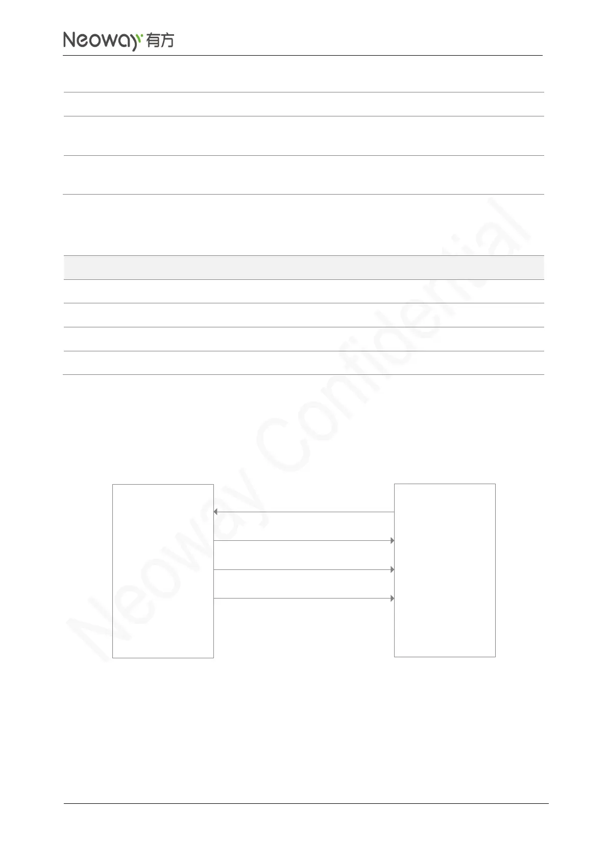
The SPI interface operates at 1.8 V. It supports a maximum frequency of 50 MHz and only host mode.
Figure 3-33 and table show the SPI connection.
Figure 3-33 SPI connection
SPI_MOSI
SPI_CS_N
SPI_CLK
N75 module
(host)
SPI_MISO
MOSI
MISO
CLK
CS
SPI device
(device)
Schematic Guidelines
⚫
Note the SPI signal direction.
⚫
If the levels of slave SPI device and N75 do not match, add a level shifting circuit. Refer to
Figure 3-20 if the SPI speed does not exceed 20 MHz. Select other high-speed level shifting
chipsets if the speed exceeds 20 MHz.