EasyManua.ls Logo

Neoway N75 - Figure 3-43 SDIO SDR Timing; Figure 3-44 SDIO DDR Timing; Table 3-15 Timing Parameters of SDIO;WLAN Interface

Neoway N75
95 pages
Print Icon
To Next Page IconTo Next Page
To Previous Page IconTo Previous Page
Loading...
N75
Hardware User Guide
Copyright © Neoway Technology Co., Ltd
49
Control the impedance of SDIO interface to 50Ω.
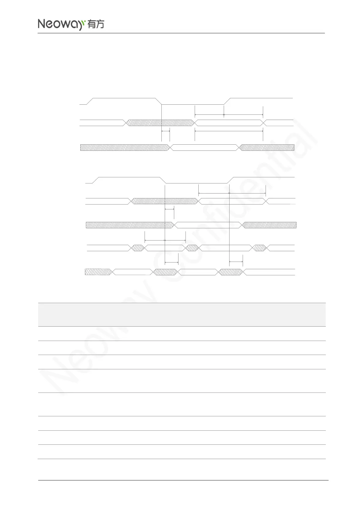
SDIO supports at most SDR 200 MHz or DDR 50 MHz. The following figures and table show the timing
and parameters of SDR and DDR modes respectively.
Figure 3-43 SDIO SDR timing
Figure 3-44 SDIO DDR timing
Table 3-15 Timing parameters of SDIO/WLAN interface
Timing Parameter
Minimum
Value
Typical
Value
Maximum
Value
Unit
SDR mode (max. 200MHz)
t(cvdrd)
Command valid time
2.4
/
/
ns
t(dvdrd)
Data valid time
2.4
/
/
ns
t(pddwr)
Delay time from data write to
transmit
-1.45
/
0.85
ns
t(pdcwr)
Delay time from command write to
transmit
-1.45
/
0.85
ns
DDR mode (max. 50MHz)
t(chrd)
Command hold time
1.5
/
/
ns
t(csurd)
Command set-up time
5.53
/
/
ns
SD_CLK
Read
Write
t(pddwr)
t(pdcwr)
t(cdvrd)
t(dvrd)
t(csurd)
t(dsurd)
t(chrd)
t(dhrd)
Command
Read
Command
Write
t(pdcwr)
t(csurd)
t(chrd)
SD_CLK
DATA
Read
DATA
Write
t(dsurd)
t(dhrd)
t(pddwr)
t(pddwr)

Table of Contents

Related product manuals