Startup Process
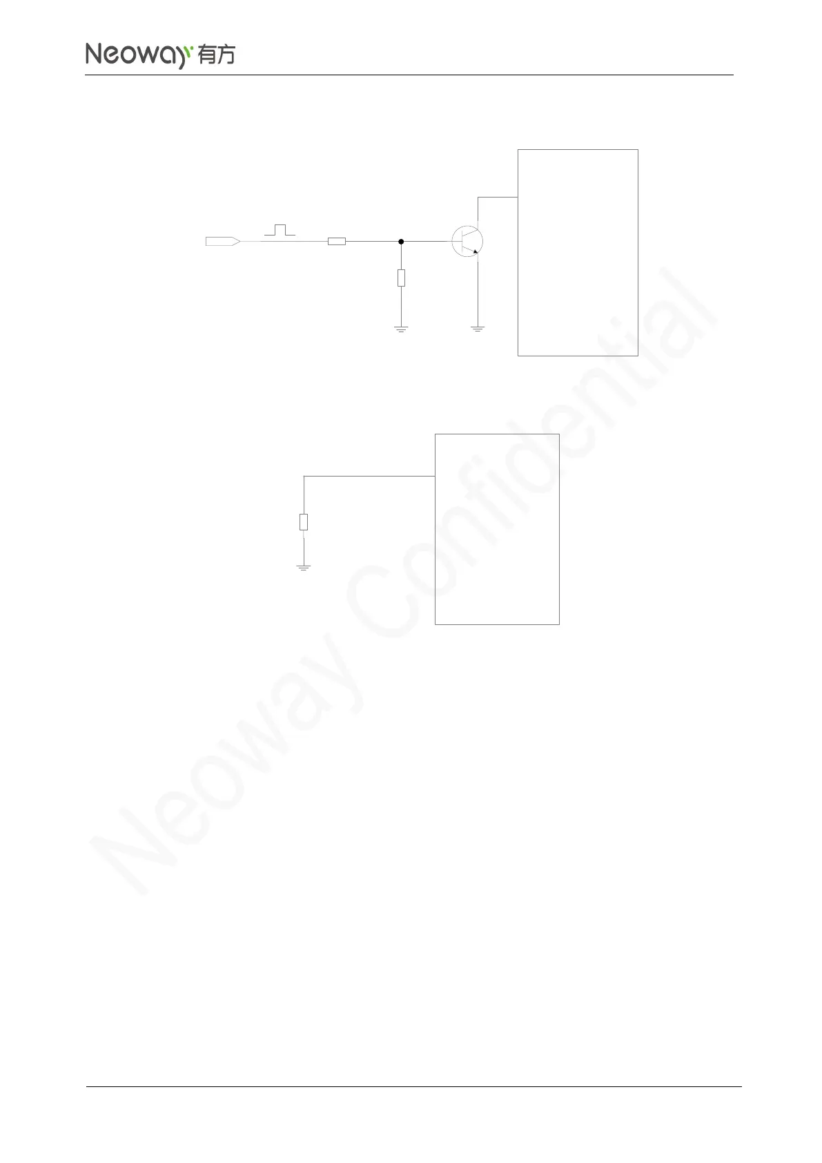
After powering up the VBAT pin, input a negative pulse of wider than 100 ms (longer than 200 ms is
recommended) into PWRKEY_N to start the module. The PWRKEY_N pin is internally connected to
the power supply through a 200 kΩ pull-up resistor. Do not connect an external resistor with large
resistance. Otherwise, the module cannot be powered up since the PWRKEY_N is input high level all
the time internally.
If the application do not have to control the ON/OFF state of the module, connect PWRKEY_N to the
ground through a 1.5 kΩ pull-down resistor. Then, the module can start automatically once it is powered
up.
Do not perform other operations on the module until it is initialized completely. If the module is powered
up but the startup process has not been completed, the states of each pin are uncertain.