Copyright © Neoway Technology Co., Ltd
PCB Design Guidelines
⚫
Do not cross other traces if possible. If crossing is inevitable, route the SPI traces perpendicular
to other traces.
⚫
Keep SPI traces far away from areas that might introduce ESD.
⚫
Surround signal traces with ground.
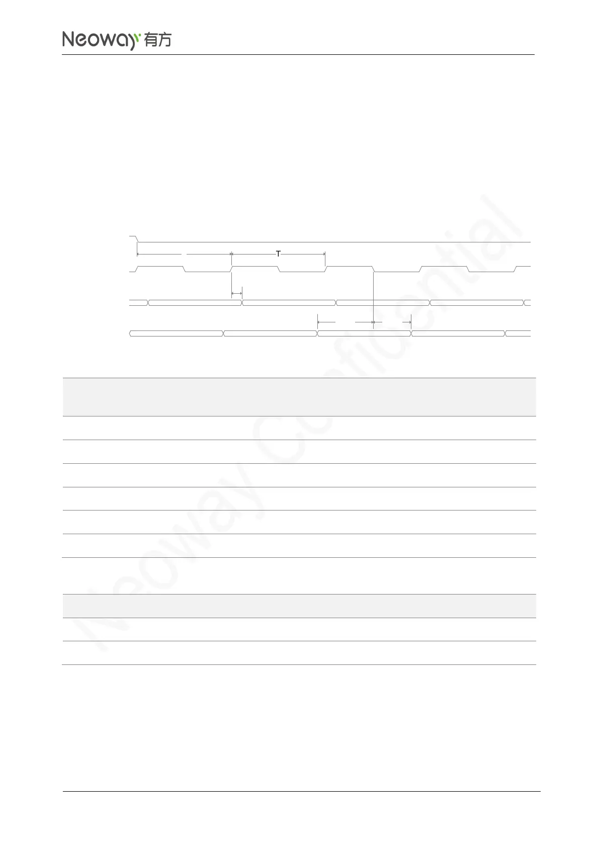
Figure 3-34 and Table 3-9 shows SPI timing and parameters respectively.
Figure 3-34 SPI timing
Table 3-9 Timing parameters of SPI interface
Embed a 2.2 kΩ pulled up resistor internally.
Embed a 2.2 kΩ pulled up resistor internally.
I2C operates at 1.8V and complies with I2C Specification, version5.0, October 2012. Theoretical rate
is up to 1 Mbps.
The I2C interface is open-drain driven and connected through an internal pull-up resistor. If you use
other pins to multiplex I2C interface, reserve a place for the external pull-up resistor. It can be used in
T
t(mov)
t(mis) t(mih)
SPI_CS_N
SPI_CLK
SPI_MOSI
SPI_MISO