EasyManua.ls Logo

Neoway N75 - Uart; Figure 3-16 Reference Design of UART Connection (with Flow Control); Figure 3-17 Reference Design of UART Connection (Without Flow Control)

Neoway N75
95 pages
Print Icon
To Next Page IconTo Next Page
To Previous Page IconTo Previous Page
Loading...
N75
Hardware User Guide
Copyright © Neoway Technology Co., Ltd
27
3.3.4 UART
Signal
Pin
I/O
Function
Remarks
UART5_TXD
46
DO
UART5 data transmitting
Used for data transmission
UART5_RXD
47
DI
UART5 data receiving
Used for data transmission
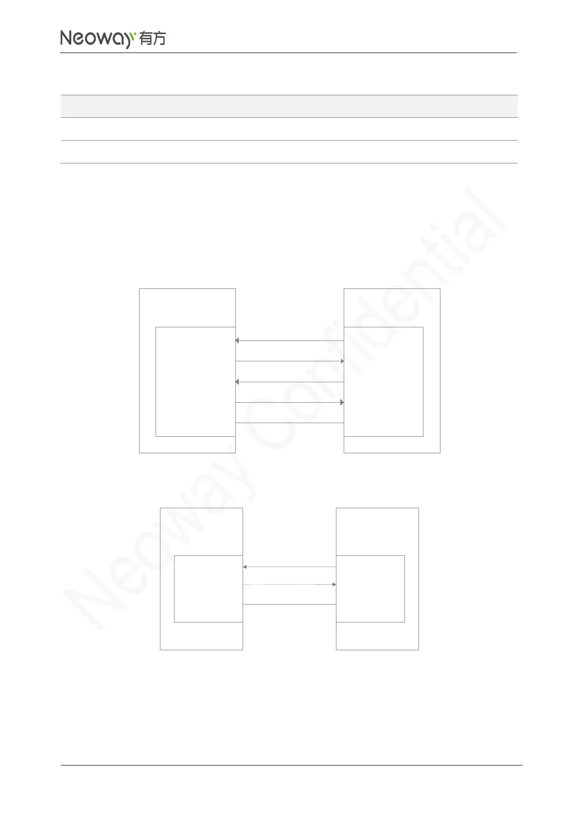
N75 provides one UART interface. To support hardware flow control, multiplex pin 51 and pin 52 as
UART5_CTS and UART5_RTS. UART interfaces support 4 Mbps at most. The level at the interfaces
1.8V. To use multiple UART interfaces, see Section 3.7 MUX Interfaces. Figure 3-16 and Figure 3-17
show the reference designs of the UART interfaces.
Figure 3-16 Reference design of UART connection (with flow control)
UART3_RXD
UART3_TXD
MCU_TXD
MCU_RXD
GND GND
N75
module
Client
UART3_CTS
UART3_RTS
MCU_RTS
MCU_CTS
Figure 3-17 Reference design of UART connection (without flow control)
UART5_RXD
UART5_TXD
MCU_TXD
MCU_RXD
GND GND
N75
module
Client
Schematic Guidelines
Note the match of signals.

Table of Contents

Related product manuals