Schematic Guidelines
⚫
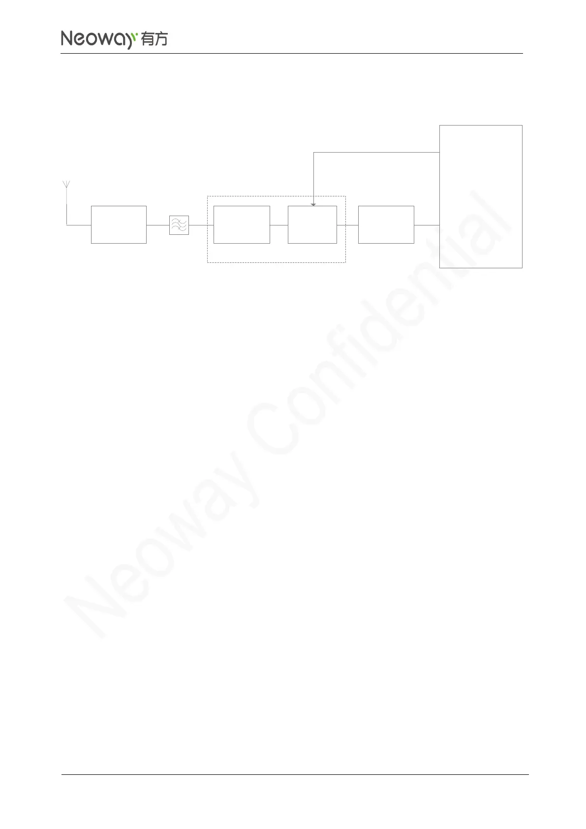
For the impedance matching circuit between N75 and GNSS antenna, refer to section 3.5.1.
⚫
If using a passive GNSS antenna, place an LNA near the feeder because the module does not
embed one internally. GNSS_LNA_EN is used to enable the external LNA. To get a better
performance, use a multi-stage LNA.
⚫
Add a SAW filter between matching network and LNA.
PCB Design Guidelines
⚫
Place the LNA as close to the antenna as possible.
⚫
Keep GNSS antenna far away from other antennas, such as main antenna and WLAN antenna.
⚫
For more details, see section 3.5.1 ANT_MAIN/ANT_DIV antenna interface.
Reference design of active GNSS antenna
After the antenna receives GNSS satellite signals, the LNA amplifies the signals first and then transmits
them to the ANT_GNSS pin of N75 through feeder and PCB traces. See Figure 3-52.