EasyManua.ls Logo

Neoway N75 - RF Interface; Figure 3-45 Bluetooth Connection

Neoway N75
95 pages
Print Icon
To Next Page IconTo Next Page
To Previous Page IconTo Previous Page
Loading...
N75
Hardware User Guide
Copyright © Neoway Technology Co., Ltd
51
Figure 3-45 Bluetooth connection
UART_TXD
UART_RXD
UART_CTS
UART_RTS
N75 module
Bluetooth chipset
BT_WAKEUP_SLAVE
BT_WAKEUP_HOST
PCM_DOUT
PCM_DIN
PCM_SYNC
PCM_CLK
UART_RXD
UART_TXD
UART_RTS
UART_CTS
BT_WAKEUP_SLAVE
BT_WAKEUP_HOST
PCM_DIN
PCM_DOUT
PCM_SYNC
PCM_CLK
BT_EN BT_EN
BT
Power
VBAT
BT_PWR_EN
POWER
Schematic Guidelines
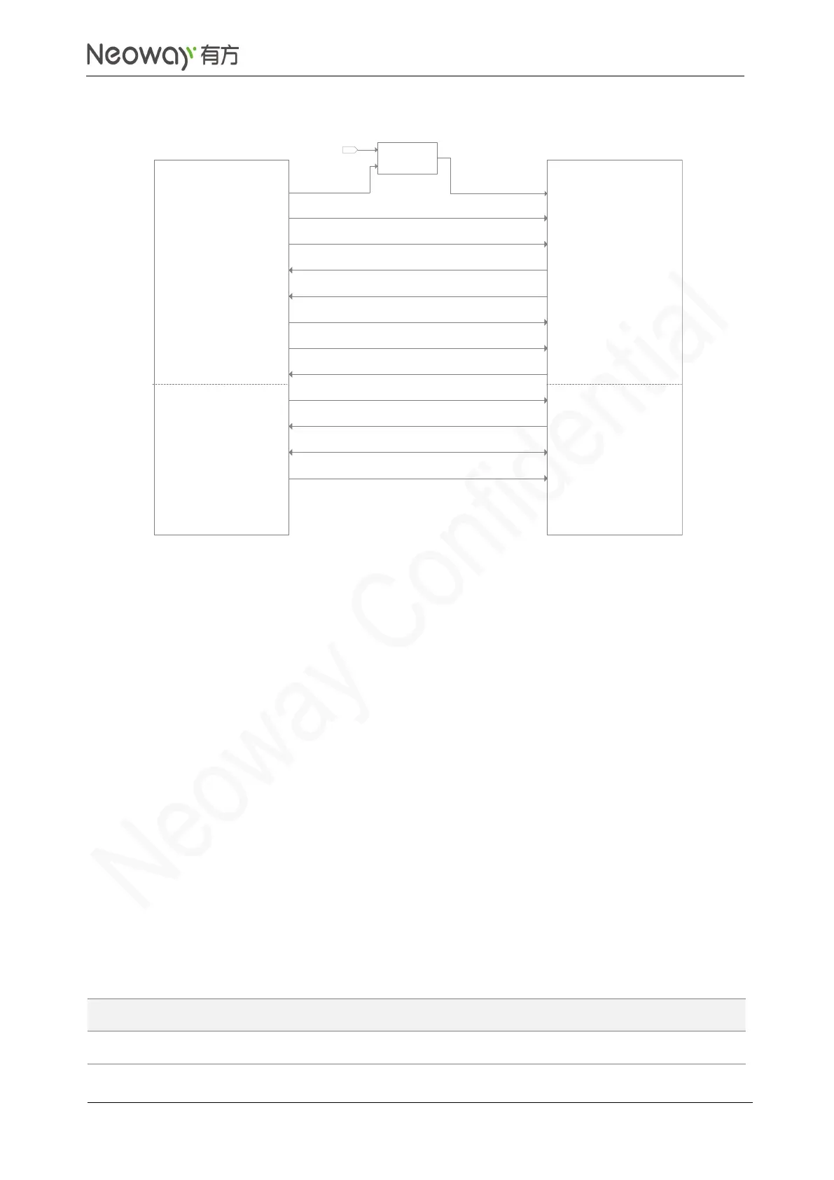
If Bluetooth and WLAN are integrated in one IC, use WLAN_PWR_EN as the power enable pin.
The Bluetooth is controlled by UART. Ensure the match of UART signals and logic levels.
BT_WAKEUP_SLAVE is the control signal for the module to wake up the Bluetooth chipset. Add
a pull-up resistor to connect it to 1.8V.
BT_WAKEUP_HOST is the control signal for the Bluetooth chipset to wake up the module and
supported by some Bluetooth chipset. Add a pull-up resistor to connect it to 1.8V.
The Bluetooth audio function is implemented through a PCM interface. If the PCM interface is
used, leave I2S_MCLK floating.
PCB Design Guidelines
Refer to the PCB design guidelines of UART and PCM.
3.5 RF Interface
Signal
Pin
I/O
Function
Remarks
ANT_MAIN
76
AI/O
2G/3G/4G main antenna
50Ω impedance

Table of Contents

Related product manuals