MX Series Voice Gateway User Manual
New Rock Technologies, Inc. 25
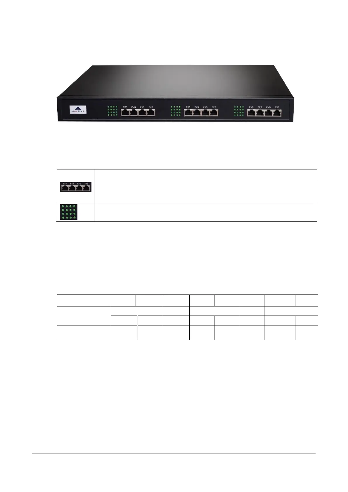
Figure 1-10 MX60E Front Panel
Table 1-17 Description of MX60E Front Panel
Three interface slots; each has four RJ45 sockets; each RJ45 socket can correspond with four pairs of
analog lines.
Note: Numbers of interface slots vary from different configuration.
Matrix of 4 x 4 LED status indicators on the interface card
Each RJ45 socket has 8 pins leading out 4 pairs of analog telephone or trunk lines in agreement with the
pair specifications for Ethernet interfaces, whose corresponding relations can be seen in the table below.
CAT-5 cables are used to connect the interface card and distribution panel in equipment installation.
Standard RJ11 telephone lines can be used to plug in a RJ45 socket. The telephone/trunk lines are connected
to the 3
rd
pair of pins for simple call test.
Table 1-18 Pin Specifications for MX60E RJ45 Socket Port