MX Series Voice Gateway User Manual
New Rock Technologies, Inc. 29
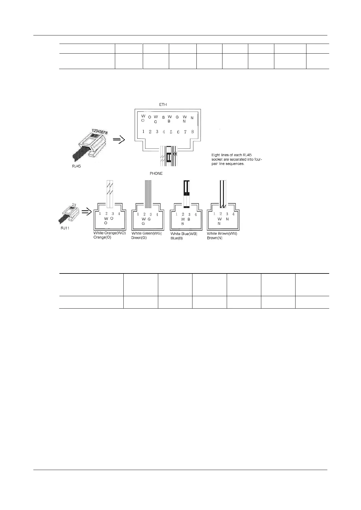
Figure 1-14 Schematic Diagram of MX120G Subscriber Line Connection
Table 1-26 Corresponding Relation Between MX120G RJ45 Socket and Line Number
RJ45 Socket No.
(From Left to Right)
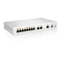
There is a 6 × 4 LED indicator matrixes on the left side of interface board. Each row of LED indicator
matrixes matches four telephone lines on a RJ45. The first row on the left matches Line 1-4 respectively
from top to bottom, the first row on the right matches Line 21-24 respectively from top to bottom, and the
middle rows in the same manner.
LED indicators are used for multiple purposes as follows:
Line status indication: this is the most common mode during normal use of equipment. In this mode, if
a line is idle, the indicator corresponding to it goes off; if a line is in call or in use status (such as ringing,
offhook) the indicator corresponding to it goes on.
Line type indication: this is the mode for cable wiring check when installing the equipment. This mode
can be entered by disconnecting Ethernet cables (Both WAN and LAN ports must be disconnected) at
installation stage. After entering this mode, steady on LED indicates that the corresponding line is
equipped as analog subscriber line type, blinking LED indicates that the corresponding line is equipped
as analog trunk line type, off LED indicates that the corresponding line is not equipped or not ready for
use.
System operation status indication: this is the mode for displaying information on system operation of
equipment in specific conditions. Usually, this mode is entered when some prompts are required to give