MANUALE DI ASSISTENZA
ITALIANO
BR 601 / BR 651 / BR 751 / BR 751 C 909 6424 000(3)2007-12
87
IMPIANTO ELETTRICO
RICERCA GUASTI (Continua)
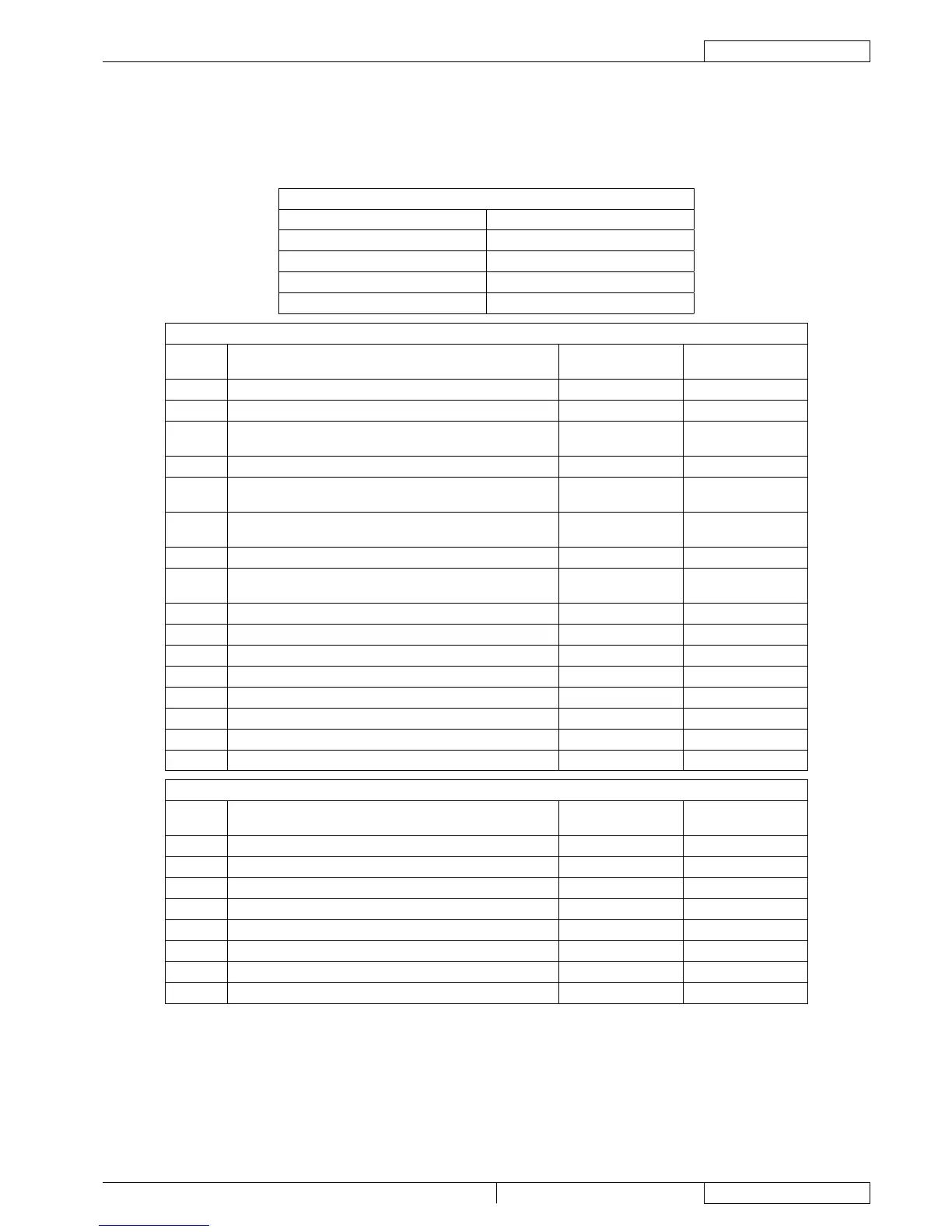
RIFERIMENTO COLLEGAMENTI DELLA SCHEDA ELETTRONICA FUNZIONI
Connettori
Legenda:
J1 Ingressi/uscite plancia
J2 Ingressi/uscite ausiliari 1
J3 Ingressi/uscite ausiliari 2
J4 Attuatore testata portaspazzole
J5 Ventola
J1
PIN Descrizione
Tensione di
riferimento
In/out scheda
elettronica
1 Alimentazione logica da chiave (+) 24 V In
2 Alimentazione plancia (-) 0 V Out(**)
3
Ritorno da interruttore di sollevamento/abbassamento
testata portaspazzole
Indef (0 V) In
4 Ritorno da interruttore pressione supplementare Indef (0 V) In
5
Ritorno da interruttore attivazione/disattivazione impianto di
aspirazione
Indef (0 V) In
6
Alimentazione LED interruttore di sollevamento/
abbassamento testata portaspazzole (LED1)
Indef (0 V) Out
7 Alimentazione LED interruttore pressione supplementare Indef (0 V) Out
8
Alimentazione LED interruttore di attivazione/disattivazione
impianto di aspirazione
Indef (0 V) Out
9 Alimentazione LED VERDE batterie Indef (0 V) Out
10 Alimentazione LED GIALLO batterie Indef (0 V) Out(**)
11 Alimentazione LED ROSSO batterie Indef (0 V) Out
12 Uscita pressostato 0 - 5 V Out(**)
13 Ingresso regolazione elettrovalvola 1 Indef (0 V) In
14 Ingresso regolazione elettrovalvola 2 Indef (0 V) In
15 Ingresso avvisatore acustico Indef (0 V) In
16 Uscita elettrovalvola (ripetizione di J2.2) Indef (0 V) Out
J2
PIN Descrizione
Tensione di
riferimento
In/out scheda
elettronica
1 Alimentazione elettrovalvola 24 V Out
2 Alimentazione elettrovalvola Indef (0 V) Out
3 Alimentazione attuatore tergitore 24 V Out
4 Alimentazione attuatore tergitore Indef (0 V) Out
5 Ritorno da microinterruttore sedile Indef (0 V) In
6 Ingresso pressostato 0 - 5 V In
7 Alimentazione ausiliari (+) +24 V Out(**)
8 Alimentazione ausiliari (-) 0 V Out(**)