ITALIANO
MANUALE DI ASSISTENZA
88
909 6424 000(3)2007-12 BR 601 / BR 651 / BR 751 / BR 751 C
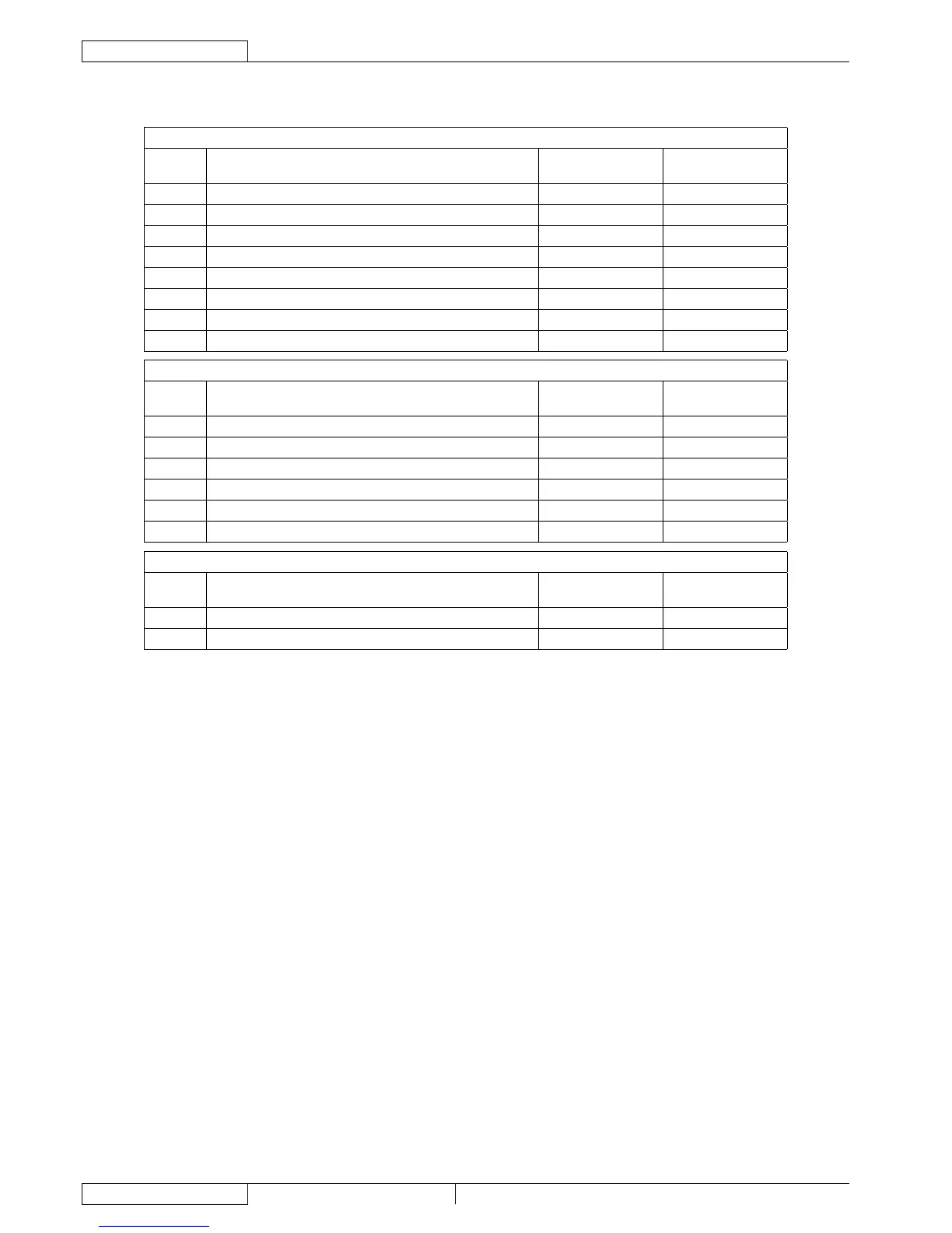
IMPIANTO ELETTRICO
Connettori (Continua)
J3
PIN Descrizione
Tensione di
riferimento
In/out scheda
elettronica
1 Alimentazione ausiliari (+) 24 V Out(**)
2 Alimentazione ausiliari (+) 24 V Out(**)
3 Alimentazione ausiliari (-) 0 V Out(**)
4 Ingresso da segnale macchina in movimento Indef (0 V) In
5 Ingresso da segnale retromarcia Indef (0 V)(*) In
6 Ingresso consenso testata portaspazzole a rullo Indef (0 V) In
7 Uscita inibizione impianto di trazione Indef (0 V) Out(**)
8 Uscita avvisatore acustico Indef (0 V) Out(**)
J4
PIN Descrizione
Tensione di
riferimento
In/out scheda
elettronica
1 Alimentazione martinetto testata Indef Out
2 Alimentazione martinetto testata Indef Out
3 Martinetto ritorno microinterruttore m0 Indef (0 V) In
4 Martinetto ritorno microinterruttore m1 Indef (0 V) In
5 Martinetto ritorno microinterruttore m2 Indef (0 V) In
6 Alimentazione comune microinterruttore martinetto 0 V Out
J5
PIN Descrizione
Tensione di
riferimento
In/out scheda
elettronica
1 Alimentazione ventola 24 V Out
2 Alimentazione ventola Indef (0 V) Out
(*) Pull-up a 24 V
(**) Uscite garantite anche in caso di ALARM, vedere tabelle dei codici di errore segnalati dai LED