User Manual N11
Installation
Industrial PC
www.noax.comPage 32 of 120 3085-US-2.4
8.5.3
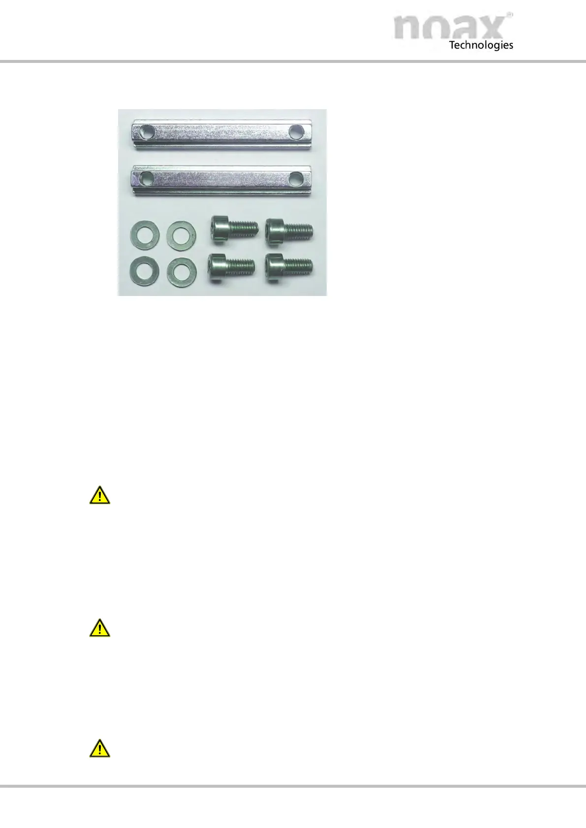
T‐slot nuts
The two guide rails with T‐slots at the
rear side of the Compact - C12 and
C12P enclosure can be used to install
the Industrial PC.
Two long T‐slot nuts (DIN 508 / 7 mm
deep thread) and screws (M5x10) with
washers for mounting the long T‐slot
nuts are included in the scope of
delivery
Fig. 12: Long T‐slot nuts and screws
Usage:
D Install the IPC directly to a installation surface, e.g. Control cabinet door.
D Install the IPC onto the optional device and wall brackets.
8.5.4
Stoppers in the T‐slots at the rear side of enclosure
At the top end of the two T‐slots in the housing rear panel, two stoppers (= short T‐slot
nuts) are firmly inserted at the factory. These stoppers are there for safety reasons
while installing or removing the Industrial PC.The IPC enclosure can slip on the long
T‐slot nuts only to the point where the stoppers are inserted. Therefore a slipping thru
of the long T‐slot nuts is prevented and the device cannot fall down.
Warning
For safety reasons, never remove the fixed small T‐slot nuts (stoppers). Make sure that
the long T‐Slot nuts and the stoppers are securely attached.
8.5.5 VESA 100 mounting option
There are four threaded holes in the rear side of the Industrial PC as per
“VESA (FDMI™) standard” - variant VESA MIS‐D, 100, C.
(100 mm / 3.9 inches distance in a square, M5 thread, depth 7.5 mm / 0.3 inches)
In condition of delivery mounted screws only protect the threaded holes.
These screws are not suitable for mounting the device.
8.5.6 VESA 75 mounting option
There are four threaded holes in the rear side of the Industrial PC as per
“VESA (FDMI™) standard” - variant VESA MIS‐D, 75, C.
(75 mm / 3.0 inches distance in a square, M5 thread, depth 7.5 mm / 0.3 inches)
In condition of delivery mounted screws only protect the threaded holes.
These screws are not suitable for mounting the device.