User Manual N11
Connectors and interfaces
Industrial PC
www.noax.comPage 50 of 120 3085-US-2.4
9.6
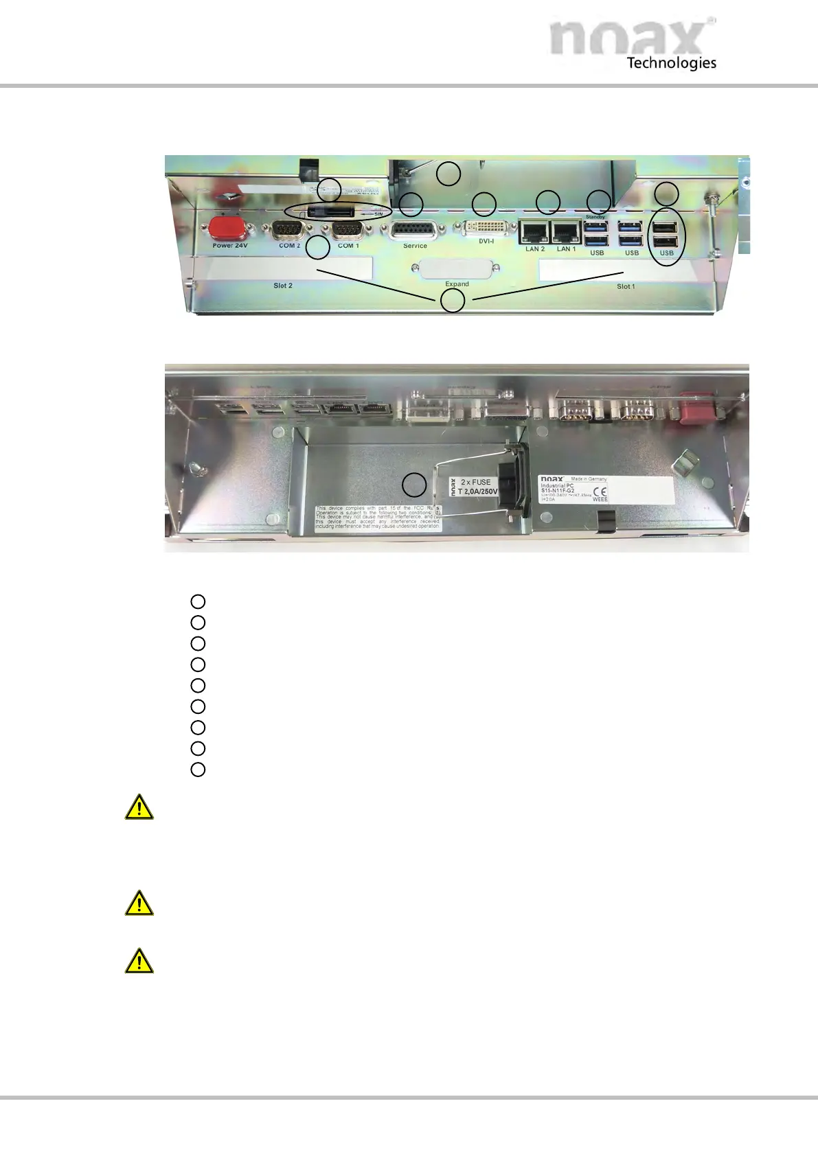
Connector area of S15‐G2 and S19
Fig. 41: Connector area of S15‐G2 with N11G mainboard
Fig. 42: Area with mains input connector and fuses
Free PCI/PCI Express card slots
Two USB 2.0 ports
Four USB 3.0 ports
Two LAN ports with status LEDs
DVI monitor port
Service port
SIM card slot
Two COM interface ports
Area with mains input connector and fuses
W
arning
Use only the mains power cord that was supplied with the device!
Only this cable used in conjunction with the safety catch from the mains input connec
tor can ensure secure locking of the plug connection.
Warning
Please ensure that the mains power cord is not damaged.
Warning
Connect and disconnect all device connectors only when de‐energized.