User Manual N11
Operation
Industrial PC
3085-US-2.4 www.noax.com Page 63 of 120
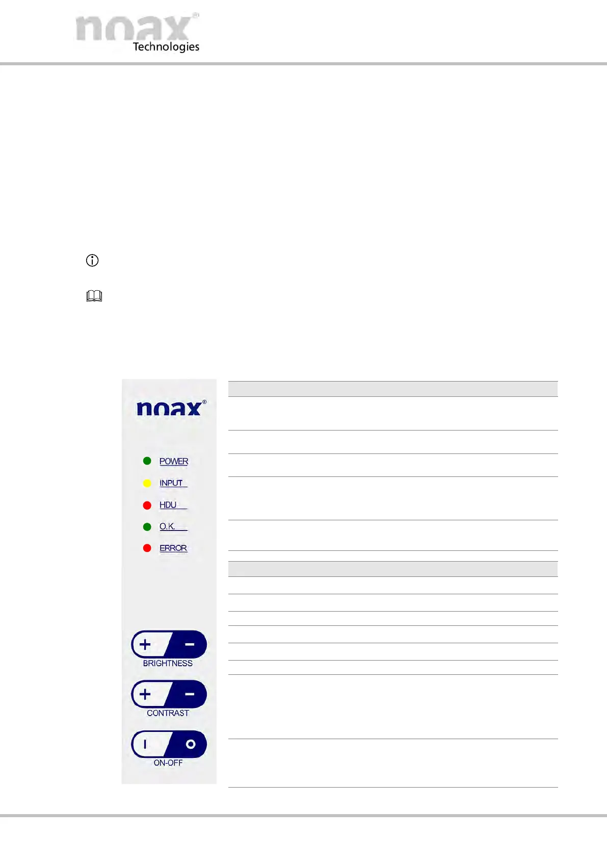
10.4 Operation and display elements for device type S12
All operation and display elements are located in the control panel on the front at the
right‐hand edge of the housing. The control panel consists of touchscreen keys and
indicator lights (LEDs).
10.4.1
General key information
D The INPUT LED lights up / flashes when a key is pressed.
D The keys should be pressed as close to the center of their respective symbol as
possible.
Operation and display element functions can be changed, limited, or deactivated using
the nSMART™ software.
Information on the operation and functionality of the nSMART™ software can be found in
Chapter 11.
10.4.2 Control panel
The following overview describes the functions as per the factory default settings.
D Lights up when the Industrial PC is turned on.
D Flashes in standby mode.
D Lights up when a valid input is made.
D Indicates hard drive activity.
D Lights up when the Industrial PC is operational.
All of the parameters monitored by the MCU are
within the limits. (see section 11.1
.)
D Lights up when an error or a critical event
occurs with the Industrial PC hardware.
D Increases display brightness.
D Reduces display brightness.
D Switches the Industrial PC on.
D Switches the display backlight on.
D Wakes up IPC from standby.
D Resets the mainboard.
D Switches the Industrial PC off.
D Switches the display backlight off.
D Shutdown the software.
Fig. 51: Operation and display elements S12