User Manual N11
Connectors and interfaces
Industrial PC
3085-US-2.4 www.noax.com Page 47 of 120
9.2 Connector area in general
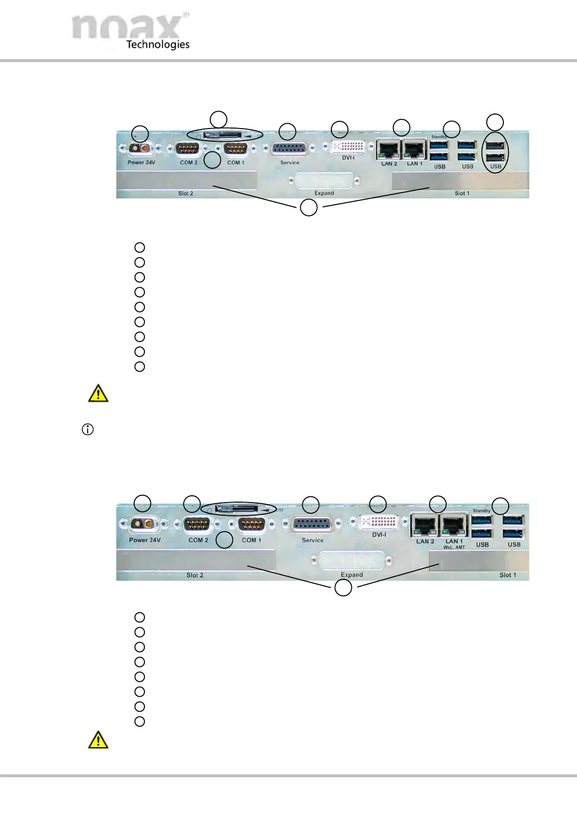
Fig. 37: Connector area using the example of the mainboard N11G
Free PCI/PCI Express card slots
Two USB 2.0 ports
Four USB 3.0 ports
Two LAN ports with status LEDs
DVI monitor port
Service port
SIM card slot
Two COM interface ports
Power supply
W
arning
Connect and disconnect all device connectors only when de‐energized.
There are no USB 2.0 ports available in the mainboard N11C variant.
The openings in the connector area are covered in this case.
9.3 Connector area C12 and C12P
Fig. 38: Connector area of C12X‐N11G
Free PCI/PCI Express card slots (Slot 1 low profile PCI/PCIe slot)
Four USB 3.0 ports
Two LAN ports with status LEDs
DVI monitor port
Service port
SIM card slot
Two COM interface ports
Power supply
W
arning
Connect and disconnect all device connectors only when de‐energized.