NORD MODULAR G2 V1.1 11. Module reference: The Oscillator group
Page 123
T
TT
T
H
HH
HE
EE
E
S
S S
S
E
EE
EM
MM
MI
II
I
(
( (
(
O
OO
OR
RR
R
F
F F
F
R
RR
RE
EE
EQ
QQ
Q
/P
/P/P
/P
A
AA
AR
RR
RT
TT
T
/F
/F/F
/F
A
AA
AC
CC
C
)
) )
)
K
KK
KN
NN
NO
OO
OB
BB
B
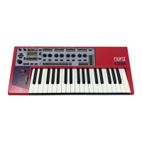
Changes the coarse tuning of the oscillator. Ranges: depending on frequency display mode (see
above).
T
TT
T
H
HH
HE
EE
E
C
C C
C
E
EE
EN
NN
NT
TT
T
K
KK
KN
NN
NO
OO
OB
BB
B
Adjust the fine tuning of the oscillator. The range is +/- half a semitone divided into 100 steps.
Click on the triangle above the knob to reset the fine tuning to the current coarse tuning value
(see above).
P
PP
P
I
II
IT
TT
TC
CC
CH
HH
H
M
M M
M
O
OO
OD
DD
DU
UU
UL
LL
LA
AA
AT
TT
TI
II
IO
OO
ON
NN
N
There are one or more Dynamic Control/Audio inputs for modulating the pitch on the os-
cillators. There can also be a pitch modulation attenuator next to the input of Attenuator
Type II. See “Pitch modulation” on page 33 for more info.
S
SS
S
Y
YY
YN
NN
NC
CC
C
M
M M
M
O
OO
OD
DD
DU
UU
UL
LL
LA
AA
AT
TT
TI
II
IO
OO
ON
NN
N
The Sync input is used for synchronizing the oscillator with a control source, which could
be another oscillator, an LFO or the keyboard gate signal. Synchronization forces the os-
cillator to restart its waveform cycle, in sync with the signal of the controlling device. The
oscillator will restart whenever a signal present at the sync input increases from 0 units to anything above
0 units. The oscillator signal usually restarts on the 0 crossing from negative to positive value after having
received a sync signal.
The pitch of the controlling oscillator will interact with the controlled oscillator pitch. For a traditional
synthesizer sync-sound, start with the two oscillators to the same pitch and connect only the sync-con-
trolled oscillator to an output. Turning the tuning knob or modulating the pitch of the sync-controlled
oscillator will produce radical changes in the timbre. See “Sync” on page 34 for more information.
S
SS
S
H
HH
HA
AA
AP
PP
PE
EE
E
A
AA
AN
NN
ND
DD
D
S
S S
S
H
HH
HA
AA
AP
PP
PE
EE
E
M
M M
M
O
OO
OD
DD
DU
UU
UL
LL
LA
AA
AT
TT
TI
II
IO
OO
ON
NN
N
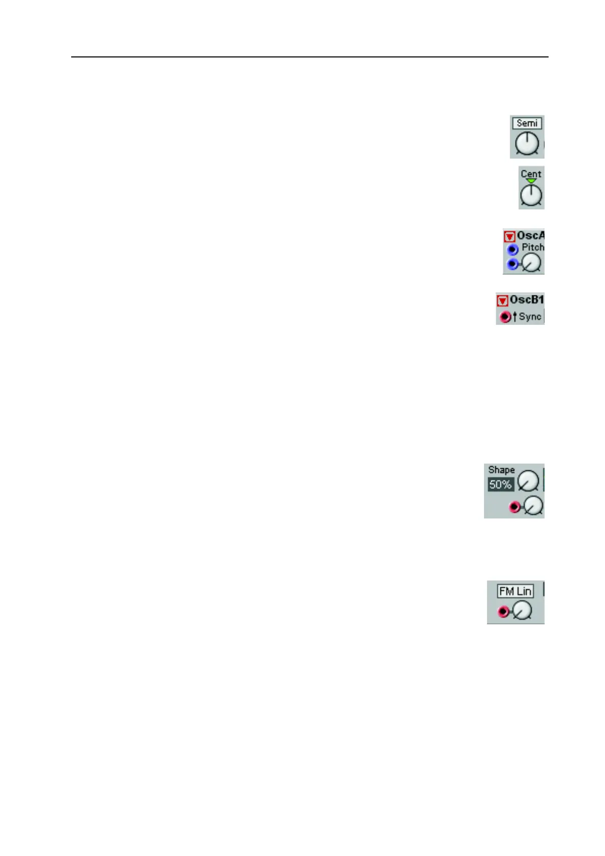
Use the Shape knob to set the initial shape of waveform. The shape range is from 50%
to 99%.
There is also an input for controlling the shape of the selected waveform from a modu-
lator, starting at the initial value set with the Shape control. The modulation amount is
determined by the rotary knob next to the input of Attenuator Type I. See page 33 for modulation ex-
amples.
FM L
FM LFM L
FM L
I
II
IN
NN
N
/FM T
/FM T/FM T
/FM T
R
RR
RK
KK
K
Some oscillators feature an FM scroll button in combination with an FM input and an
attenuator of Attenuator Type II. A signal on the FM input will affect the oscillator sig-
nal frequency according to the following: