1010/2020 INSTALLATION AND PROGRAMMING MANUAL PAGE 23
COPYRIGHT © 2000, NOTIFIER INERTIA PTY LTD
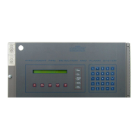
CPU TERMINATIONS
CPU 1010/2020 General Isolate and General Fault Relays
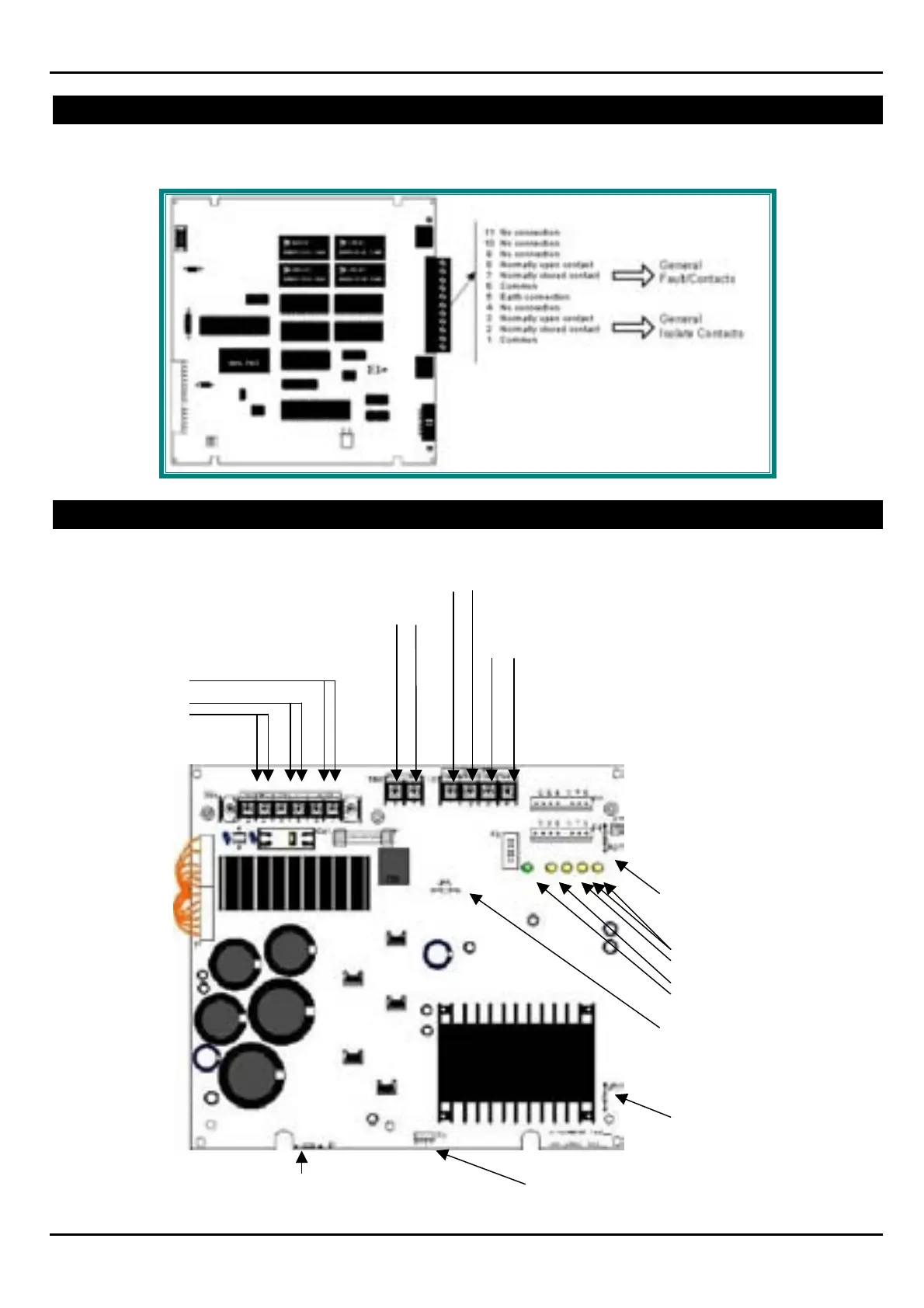
POWER SUPPLY TERMINATIONS
Neutral
Earth
Cut R27 to disable Earth Fault
Detection.
LED Indicators
Earth Fault
Battery Fail
AC Power Fail
NiCad High Charge Rate
JP5: Cut to make notification
appliance power on TB3
Terminals 3 and 4 a resettable 2-
amp maximum circuit.
JP2: must be cut otherwise a
short on the 24vdc power
(Terminals 3 and 4) would register
incorrectly as a loss of primary
(AC) power.
+ - Resettable Power
24V DC (20.4-26.4, 200 mV ripple), 1 amp
maximum. Filtered and resettable. Power-limited.
27.6 V DC, supervised and power-limited.
Fast charge = 2 amps,
Trickle charge = 20 mA.
Battery + -
Non Resettable Power
Power-limited, filtered, non-resettable, 3 amps (in alarm)
maximum. JP5 may be cut to convert this power (TB3
Terminals 3 and 4) to a resettable, 2-amp maximum circuit.
This output can also be used to power ACS series
Annunciators (do not cut JP5).
JP1: When employing an NR45-24/E or CHG-120,
Remote Battery Charger, JP1 must be cut.
MPM-2 Voltmeter/Ammeter Connector
Circuit Breaker
and Fuse are
by- passed for
use in Australia