1010/2020 INSTALLATION AND PROGRAMMING MANUAL PAGE 27
COPYRIGHT © 2000, NOTIFIER INERTIA PTY LTD
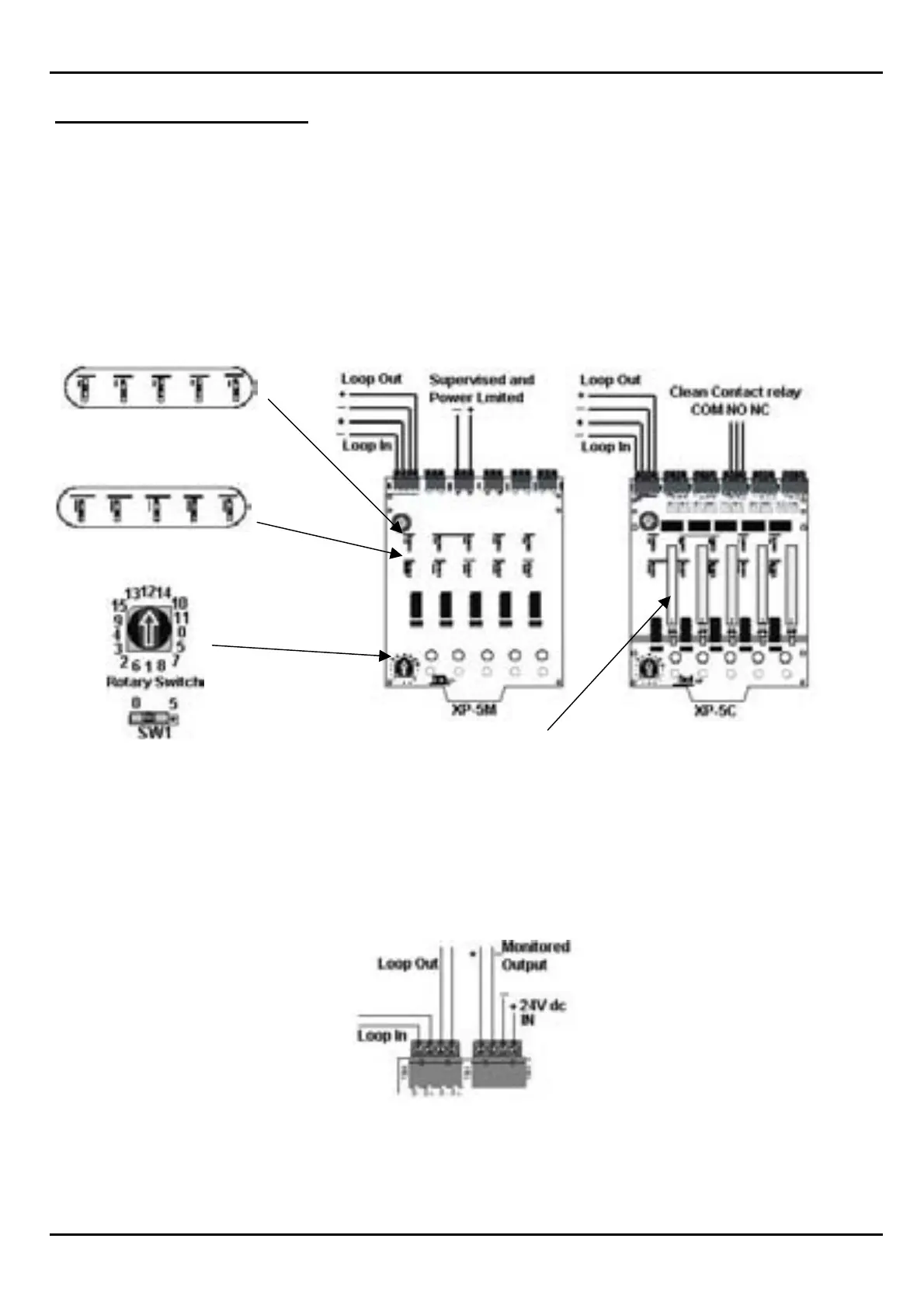
XP-5M & XP-5C MODULES
The XP-5 Control and XP-5 Monitor modules are 5 separate modules and addresses mounted on
one circuit card, the address is chosen by one rotary switch and one slide switch.
The rotary switch selects the address in increments of ten, and the slide switch selects either 0 or 5.
Eg; address 52- the rotary switch will be 5, and the slide switch will be 0.
Address 52 will be the third point on the XP-5 card.
The wiring of both the XP-5C and XP-5M are wired exactly as the CMX-2 and MMX-101 devices,
the only difference being that they share the same loop connection.
Note: Each output on the XP-5C is selectable via a switch.
Monitored output = Switch Depressed (Above Line)
Relay Output = Switch Not Depressed (Below Line).
Monitored output circuits are to be wired as per a CMX-2 and connected to the XP5-C as shown.
Address Sw1-5 set ON,
If not used, set OFF.
For Future Use, Set
SW1-5 Off