1010/2020 INSTALLATION AND PROGRAMMING MANUAL PAGE 29
COPYRIGHT © 2000, NOTIFIER INERTIA PTY LTD
DIP-SWITCH SETTINGS
The following section indicates the typical Dip-switch settings for Annunciators (SCS-8, ACM-16AT,
ACM-8R, ACM-32A, LDM-32, LDM-32R, LCD-80 and LCD-80TM)
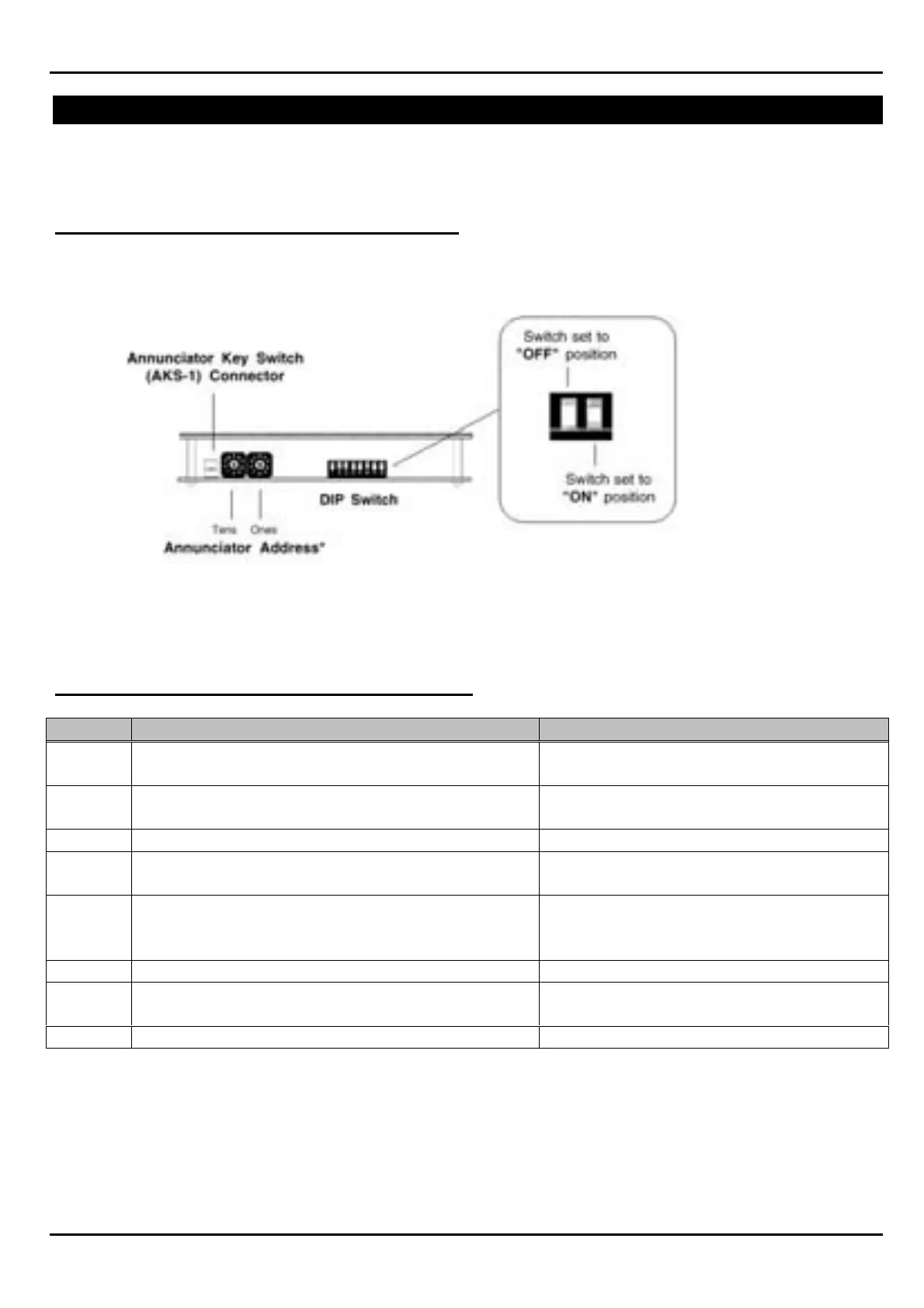
SETTING ANNUNCIATOR BOARD ADDRESSES:
Typical Annunciator address selection method
The first decimal dial on the left-hand side selects the address in unit of ten, the second dial selects
the address in units of one.
SCS-8 FAN CONTROL MODULE ANNUNCIATOR
SW ON OFF
1 –10sec to duct detector latching time
(Standard time = 60 Seconds)
No Change
2 –20sec to duct detector latching time
(Standard time = 60 Seconds, )
No Change
3 Instant Fan Faults Fan Faults Delayed 30 Sec
4 Addresses 33-64 Are ALL additional
latching fire trips.
Addresses 33-63 are for SCE-8
Address 64 is the only FTR.
5 Global mode Reset Activated ie: Broadcast
latching plant trip reset to all SCS-8’s
Global Mode Reset Disabled: Ie:
plant trip reset restricted to current
SCS-8.
6 Latching A/C Trip Non-Latching A/C Trip
7* Fire Mode LED From Z240. Fire Mode Led, from Common Alarm
LED.
8 EOL Resistor for RS485 EOL resistor out of circuit.
* With the SCS-8 there is a choice as to how a Fire Mode trip is activated.
Dip Switch 7 when ON- selects Z240 as the input to the SCS-8 to activate Fire Mode.
Dip Switch 7 when OFF- selects the common alarm LED as the input for the SCS-8 Fire Mode Trip.