PAGE 28 1010/2020 INSTALLATION AND PROGRAMMING MANUAL
COPYRIGHT © 2000, NOTIFIER INERTIA PTY LTD
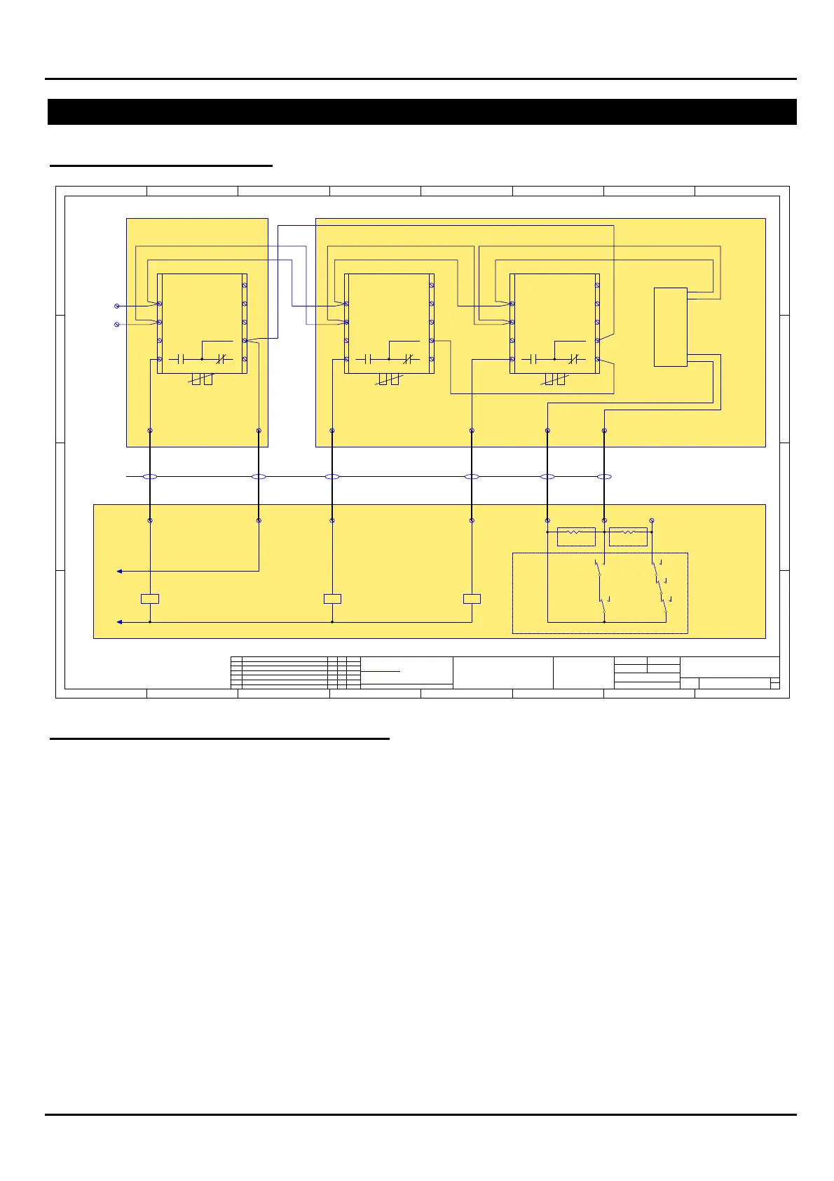
1668 FAN CONTROLS
TERMINATION OF MODULES
1 2 3 4 5 6 7 8
A
B
C
D
87654321
D
C
B
A
Rev
Size
Drg.
No.
title
Sheet:
Drawn/
Traced
Engineer
Design
Approved
This Drawing must not be used for Construction
unless signed as approved
Of:
7 Columbia Court,
Norwest Business Park
Baulkham Hills NSW 2153
AUSTRALIA
Tel
Fax
Email: support@inertia.com.au
A3
No. Revision - revise on CAD. Do not amend by hand Eng. App. Date
Copyright
This document is & shall
remain the property of
Notifier Inertia Fire Systems
Unauthorised use of this
document in any way is
prohibited.
Drawing File No.
C
O
61 2 9894 1444
61 2 9899 4156
E:\JOBS\..\Nifs_fan.sch
FTR FAN START FAN STOP
LOOP
ANALOGUE
+24FTR FAN START FAN STOP
REPEAT FOR EACH FAN
TYPICAL FAN INDICATION CONTACT ARRANGEMENT
47K
FAULT [ OPEN CCT ]
RUN [ CLOSED CCT ]
STOP [ 47K RES ]
FAN CONTROLS
FIELD I/O-VER3
1 1
G.W.25/2/00
NIFS_FAN
RUN
FS
AFR AFR
SR
COMM RUN FAULT
FR
STOP
INDICATION
SR =START RELAY
AFR =AIR FLOW RELAY
FR = FAN RUN RELAY
FS = FAN STOP RELAY
FTR
FTR
SUPPLY
POWER
MECHANICAL SERVICES BOARD
PFR PFR
PFR = PHASE FAILURE RELAY
TABS TO BE BROKEN TABS TO BE BROKENTABS TO BE BROKEN
A
N/O
N/C N/C
COM
N/O
+24
0V
47K
NOTE :
(A) = FAULT CONTACT NOT USED
(B) = FAULT CONTACT USED
REPEAT FOR EACH FIRE TRIP
+24
+ ANALOGUE LOOP
- ANALOGUE LOOP
MMX-101
INDICATION
-VE
+VE
LEGEND
USE ONLY RESISTOR A OR B
SEE NOTE A SEE NOTE B
VIOLET
YELLOW
BLACK
RED
FTR = FIRE TRIP RELAY
FIELD CABLING
(-)
(-)
(+)
(+)
DATA
DATA
(-)
(+)
1
2
3
4
5
6
7
8
9
CMX-2
COM
DATA
DATA
(-)
(+)
1
2
3
4
5
6
7
8
9
CMX-2
N/C
COM
N/O
DATA
DATA
(-)
(+)
1
2
3
4
5
6
7
8
9
CMX-2
APPLICATION OF FAN CONTROL MODULES
It's required that all fan controls utilise Two CMX-2's (with tabs broken) and One MMX-101 per fan.
When installing the modules on the SLC loop, always make the address on the Start CMX-2 lower
numerically than the Stop CMX-2.
eg: CMX-2 Start = L1M1
CMX-2 Stop = L1M2
MMX-101 Airflow = L1M3
NOTE:
For programming Fan Controls please consult the Programming section of the Manual