PAGE 68 1010/2020 INSTALLATION AND PROGRAMMING MANUAL
COPYRIGHT © 2000, NOTIFIER INERTIA PTY LTD
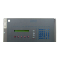
1668 (SCS-8) PROGRAMMING
Up to 16 fans (per Annunciator address, 8 with master, then further 8 with expander fitted)
Each individual fan may be programmed to either start or stop automatically in fire mode.
If a duct probe is triggered the fan will be forced to stop until a configurable time period
(30-60 seconds) after the probe clears. If there is manual intervention the fan will assume the state
presented on the switches.
There is also support for up to 32 individual latching plant trips per SCS-8.
Configuration
The examples assume an SCS-8 is installed at address 1
The addresses used are for example only. It is acceptable to use completely different
addresses. However it is important that when using different device addresses the
numerical ordering is not changed, ie: the STOP module is numerically after the START module.
The examples assume a general zone at Z200.
The examples assume floor zones from Z1-Z10.
The examples assume all necessary Annunciator points are installed. When Annunciator points
mapped to CMX's, the type ID will be AFCM and when Annunciator Points are mapped to detectors
or MMX-101's the type ID will be AINP.
It is necessary that for each bank of 4 Annunciator points (1 fan) that the first two Annunciator points
to be AFCM and the last two to be AINP for a fan to be registered as installed.
Ie: A1P1=AFCM (Start)
A1P2=AFCM (Stop)
A1P3=AINP (Fan Status)
A1P4=AINP (Duct Probe)*
*(Except for the last fan where it is OK to use the last point, ie: point 64 as AFCM for an Fire trip
relay. If the point if AINP, it will behave as all other fans ie: Duct probe at this point.)
A FAN THAT STARTS IN FIREMODE WITH ASSOCIATED DUCT DETECTOR:
Address Type Label Annunciator
Map
C.B.E
L1M1 FRCM FAN START A1P1 OR ( Z200)
L1M2 FRCM FAN STOP A1P2 ( )
L1M3 NONA FAN STATUS A1P3 ( )
L1D4 PHOD DUCT PROBE A1P4 ( )