FX / RVE
Installation and connections
EN - 12
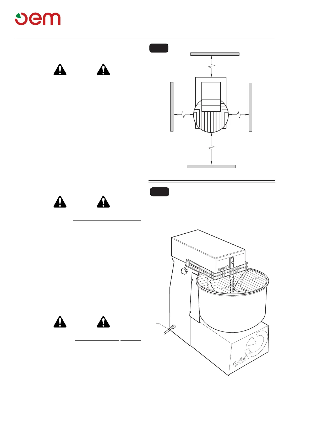
Fig. 4
400 mm
400 mm
1000 mm
400 mm
Fig. 3
1
3.3 - POSITIONING OF THE MACHINE (Fig. 3)
DANGER
Make sure that the carrying plane is suitable to
support the charges as mentioned in the chapter
"TECHNICAL SPECIFICATIONS".
The machine shall be positioned by carefully following
the instructions as reported in Fig 3, since they
indicate the minimum distances needed by the user or
technician in order to properly carry out every work and/
or maintenance operation.
3.4 - ELECTRICAL CONNECTION (Fig. 4)
DANGER
• Thepowerfeedlineshouldbeprovidedwitha
suitable omnipolar DISCONNECTING SWITCH
(automatic thermomagnetic switch or differential)
placed before the control unit main switch, with
a minimum contact opening of 3 mm.
• Theearthingsystemshouldcomplywiththelocal
electric regulations in force.
• The electric power cablesshouldcomplywith
the maximum current required by the machine,
so that the total voltage drop at full charge will
be less than 2%.
• Thespecifications of the electric power line
shouldcorrespondtothespecicationsofthe
identicationplateand to those mentionedin
thetechnicalspecicationstablethatcan be
consultedintherstpartofthisbooklet.
DANGER
Before connecting the machine with the electric
line, make sure that the DISCONNECTING SWITCH
is disconnected (line not energized), therefore:
• Connect the power cable (1) of the machine with the
disconnecting switch placed above.