FX / RVE
Installation and connections
EN - 13
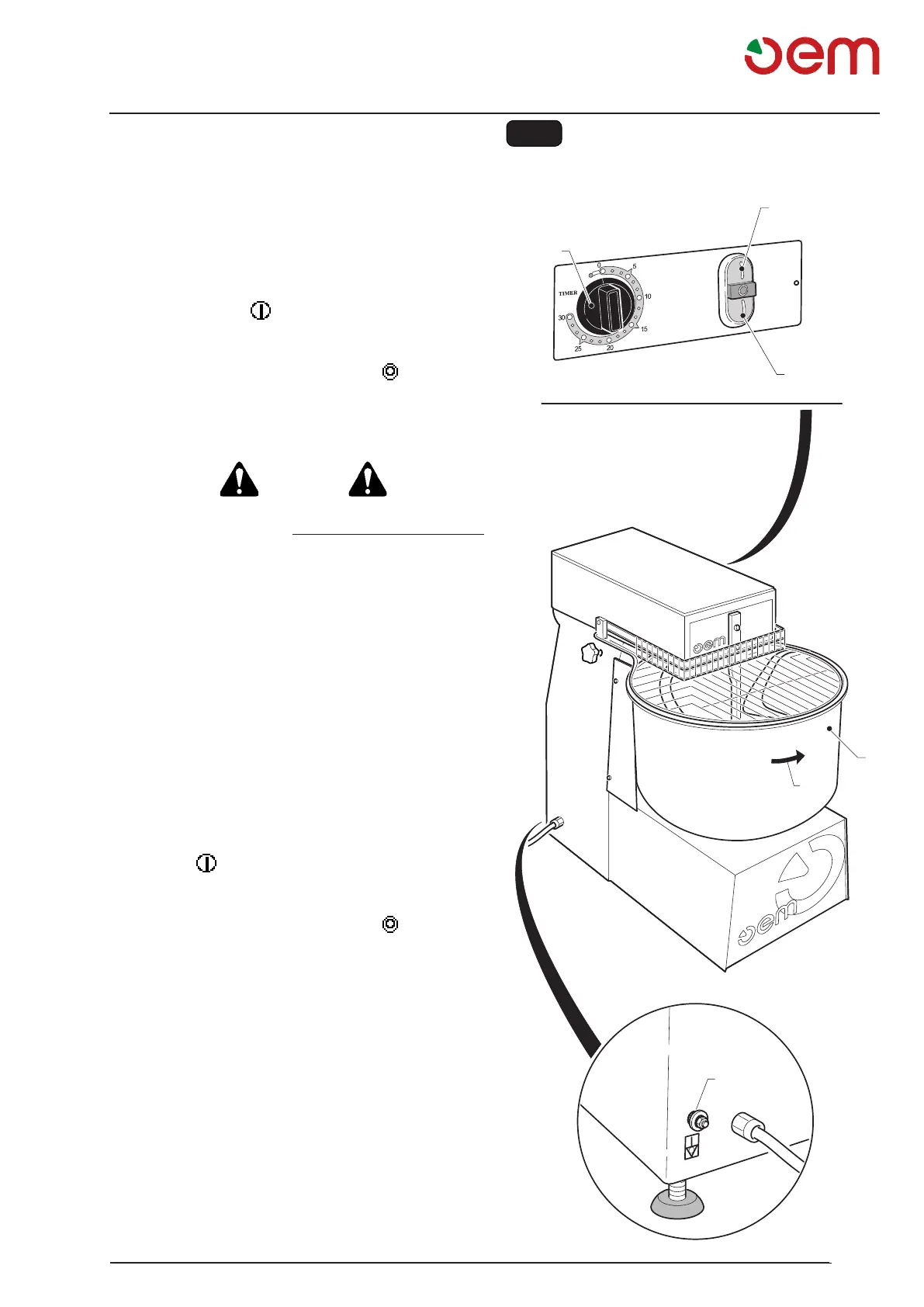
Fig. 5
2
5
1
4
3
3.4.a - Control of a correct electrical connection
(Fig. 5)
For the connection 230/400 V three phase, it is neces-
sary to check if the engine rotation is right, to do this
proceed as follows:
• Thecutoutswitchplacedatthemachineupperside
shall be positioned on “ON”.
• Turnthetimerknob(1)totheword"Timer".
• Pressthekey(2)" ".
• Visuallymakesurethecontainer(3)rotatesaccording
to the direction indicated by the arrow (4).
Disconnectthemachinebypressing" "(5)
If the rotation direction is contrary to the arrow direc-
tion, proceed as follows:
DANGER
Before making any change in the electrical connec-
tion, make sure that the DISCONNECTING SWITCH
is disconnected (line not energized), then:reverse
two of the three phase wires on the main switch and
check again the correct rotation.
3.4.b - Unipotential connection (Fig. 5)
The machine is provided with a screw (6) for unipotential
connection.
To make the connection, unscrew the screw nut (6),
connect the cable of the unipotential net to the screw
and tighten the nut again.
3.5 - FIRST START (Fig. 5)
• Thecutoutswitchplacedatthemachineupperside
shall be positioned on “ON”.
• Turnthetimerknob(1)totheword"Timer".
• Press(2)" ".
• Letthemachineidleforafewminutesandcheckif
the rotation is regular and free.
• Disconnectthemachinebypressing" "(5).