4-3
CHAPTER 4 TESTING
4.2.2 Off-Center Load Test (Cont.)
Adjustment for Analytical Balances (Cont.)
See Figure 5-3 for remaining steps.
5.Remove two Screws (3) which secure Shield (4) in place.
6.Remove Shield (4) from the balance.
7.Remove the two Screws (3) on top of the PC Board (11).
8.Remove the Hex Screws (14) and Washers (25) at the rear of the balance which secure the connectors on
the PC Board (11).
9.Disconnect the two cable connectors from the Load Cell going to J3 and J6 on the PC board as shown on
Figure 5-3.The Load Cell (9). Use cable extenders. If internal calibration option is installed, disconnect cable
to J4.
10. Carefully lift the PC Board (11) from the Base (18) there is a small cable from the Sensor Board which should
also be disconnected from the PC Board (not shown on Figure 5-3). The Load Cell (9) should now be exposed
for adjustments.
11.Reinstall the Pan (5) (Figure 5-2) into the exposed Load Cell.
NOTE:
Do not attempt these adjustments on the balance unless the balance is
free from drafts and is level. The balance is very sensitive and
adjustments will be affected.
12. Plug the power cord into the balance and turn the balance on.
13. Place 1/2 of the balance capacity on the center of the Pan (5) (Figure 5-2).
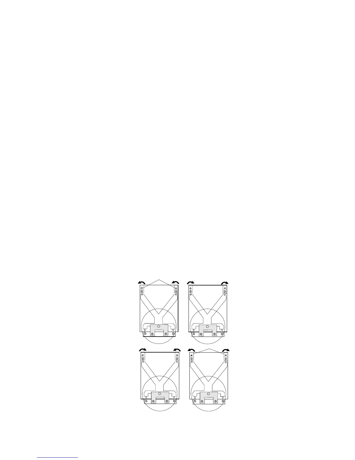
14. Press the >O/T< button to return the displayed weight to 0g. Slide mass front, back, left and right to Pan
edge. Note displayed values. Correct any errors by turning Cornerload Adjusting Screws shown in Figure
4-4 (adjust the Hex Nut portion and ensure center screw does not turn).
CD
A
B
+
-
+
-
-
+
-
+
ADJUSTMENT SCREWS
Figure 4-4. Analytical Off-Center Load Adjustments Diagram.