4-4
CHAPTER 4 TESTING
15. Repeat the Off-Center Load Test.
16. Turn the balance OFF and unplug power cord.
17. Remove the Pan (5).
18. Remove cable extenders, connect the two cable connectors from the Analytical Load Cell (9) to the Main PC
Board edge connectors J3, J6 and the Sensor Cable. The Sensor Board Cable is located at the rear of the
balance and may interferewith the operation of the balance if it is not positioned away from the Load Cell.
Dress the cables and make sure that the cables do not interfere with the Load Cell. If calibration option is
installed, connect cable to J4.
19. Reinstall the PC Board and secure with two screws (3).
20. Install the Hex Screws (14) and Washers (25) at the rear of the balance which secure the connectors on
the PC Board (11).
21. Install the Shield (4) back on the balance and secure with two Screws (3) (Figure 5-3).
22. Install the Draft Shield and secure with two Screws (2) making sure Lockswitch Cover Seal (3) (Figure 5-2)
is in place.
23. Replace the Cover Plate (6) and Pan (5) inside of the Draft Shield (Figure 5-2).
NOTE:
If the Off-Center Load Adjustment cannot be completed, refer to the
Precision Test/Adjustment.
4.2.2 Off-Center Load Test (Cont.)
Adjustment for Analytical Balances (Cont.)
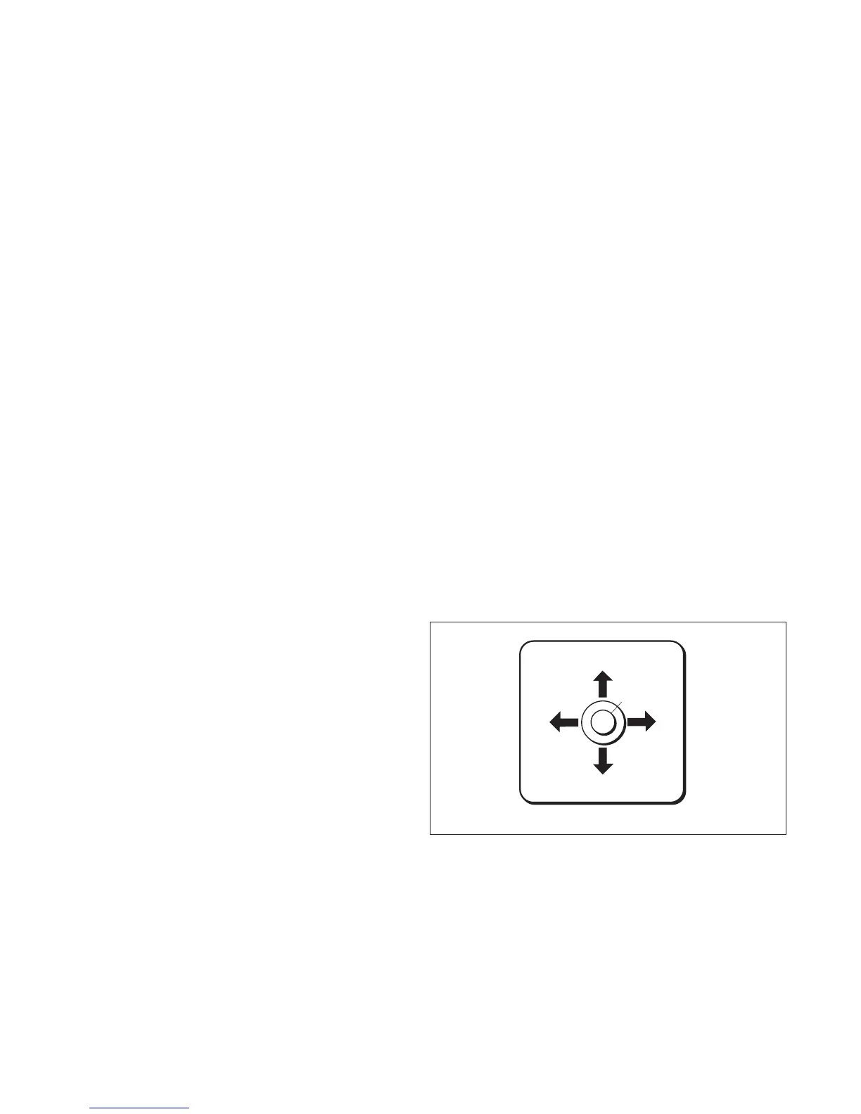
Checking the Off-Center Load
1.Level the balance.
2.Place test weight in the middle of the weighing
pan and tare.
3.Move test weight half way to the weighing pan
edge and note down the print out display values
which differ from zero with sign (see examples).
4.Compare display values with off center load
tolerance as listed in Table 4-1.
Test for Monoblock Balances
201
-10
-2
+3
+7
0
Figure 4-5. Monoblock Off-Center Load.