Oki Data CONFIDENTIAL
44871001TH Rev.6
6-17
6. MAINTENANCE MENUS
6.4.2.3 Switch scan test
This self-diagnostic menu is used to check the entry sensor and the switch.
1. Enter the self-diagnostic mode (level 1), press the [2
] or
[8
]
key repeatedly ,and
press the [6] key when the "SWITCH SCAN" is displayed in the upper row of the
display area. (Pressing the [2
]
key increments the test item and pressing the [8
]
key decrements the test item.)
SWITCH SCAN
2. Press either the [2
]
or [8] key until the desired menu item corresponding to the unit
to be tested in Table 4-3 is displayed in the lower row of the display area. (Pressing
the [2
]
key increments the test item and pressing the [8
]
key decrements the test
item.)
3. Pressing the [6] key starts the test. Name and present status of the corresponding
unit are displayed.
PAPER ROTE:PU
1=H 2=L 3=H 4=L
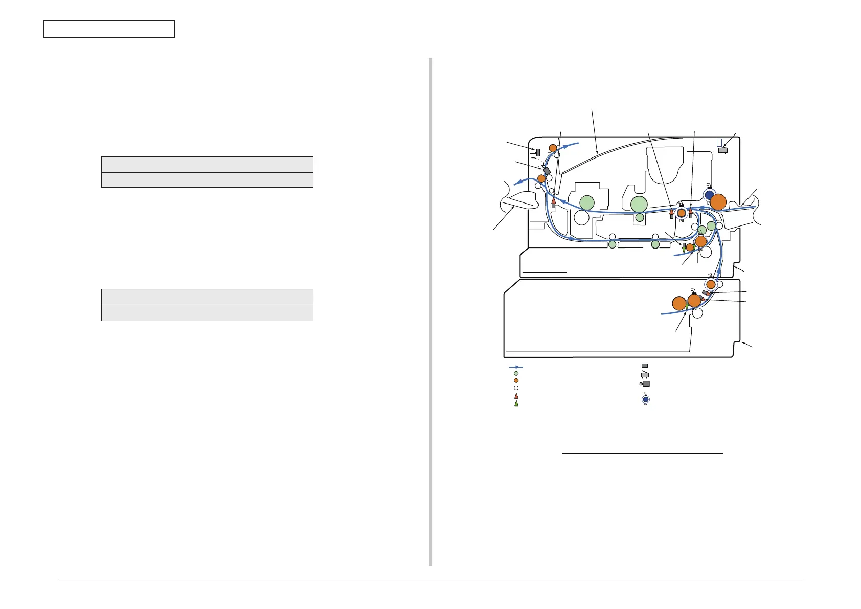
Activate the respective units. (Figure 4-1) Status of the respective units are
displayed on the corresponding areas of the LCD display. (Display changes
depending on each sensor. Refer to Table 4-3 for details.)
4. Press the [#] key to return to the status of step 2.
5. Repeat steps 2 to 4 as required.
6. Press the [4] key to exit the test. (Returns to the status of step 1.)
:Paper level indicator lever
:Driven roller
:Driving roller (Continuous rotation)
:Driving roller (Control rotation)
:Paper conveying route
:Indicating lever
:Photo sensor
:Micro switch
:Magnetic clutch
:Micro switch
Front
Back
Face up stacker
Eject Assy opening
-closing sensor
2nd Hopping sensor
2nd Entrance sensor
Face up stacker
opening-closing sensor
Paper end Sensor
Stacker Cover
opening-closing sensor
Paper end / Cassette
presence - absence sensor
Cassette presence
- absence sensor
Ejecting
sensor lever
Multipurpose tray
Tray 1
Tray 2 (option)
Entrance
sensor lever
Writing out
sensor lever
Face down stacker
The sectional view of only printer