Appendices
Appendices
A-22
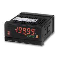
■ K3HB-S
L p
L
LEVEL
L
+
LEVEL
M
MODE
L
+
LEVEL
M
MODE
L
LEVEL
L a
L t
L
LEVEL
L
LEVEL
L
LEVEL
L
LEVEL
L
LEVEL
L 0
Linear output level L 5
L f
Communications
setting level
L 6
L
LEVEL
off
cmwt
off
CMWT:
Communications write
OFF, ON
stdby
mm.pt
0
Displayed for Linear Output Units
only.
u-no
len
sbit
prty
sdwt
20
eVen
9
.6
1
2
7
<M
<M
<M
<M
<M
bps
U-NO:
Communications
Unit No. 0 to 99
PRTY:
Parity
None, even, or odd
BPS: Baud rate
9.6, 19.2, or
38.4 kbps
LEN:
Data length
7 or 8 bits
SBIT:
Stop bits
1 or 2 bits
SDWT:
Send wait time
0 to 99 ms
M
MODE
cal
inp.a1
in-tb
20000
20.000
0
4-20
4000
4.000
<M
<M
<M
<M
M
MODE
<M
<M
<M
in-ta
4.000
<M
<M
<M
20.000
<M
k
dp
,,.,,,
0
<M
<M
amoV
nomal
0
<M
out-p
20000
4-20
dsp.a1
inp.a2
dsp.a2
inp.b1
dsp.b1
inp.b2
dsp.b2
4000
bank
0
run.pt
0
set.pt
1
wt.pt
off
<M
<M
zr.pt
off
<M
M
MODE
<M
<M
99999
99999
-19999
-19999
<M
M
MODE
M
MODE
lset.c
4-20
lset.V
1-5
lset.h
20.000
<M
<M
LSET.H: Linear
output upper limit
−19999 to 99999
lset.l
<M
LSET.L: Linear
output lower limit
−19999 to 99999
M
MODE
*Displayed only for
Communications Units.
hys
pass
1
<M
<M
<M
pass
off
init
off
test
4.000
Displayed only for
Communications Units.
LSET.C: Linear
current model
0 to 20 mA,
4 to 20 mA
LSET.V: Linear
voltage model
0 to 5 V, 1 to 5 V,
0 to 10 V
1 s min.
RUN level
Adjustment level
3 s min.
Power ON
Protect level
1 s max.
Always displayed regardless of model or settings.
Displayed only for certain models or settings.
Parameter Display
1 s min.
3 s min.
Measurement starts
Measurement stops
* Displayed when bank
selection (bnk-c) is
set to KEY.
Initial setting level
1 s max.
1 s min.
1 s max.
Output test level
Advanced function setting level
1 s max.
1 s max.
RUN.PT:
RUN/adjustment
protect
0 to 2
SET.PT:
Setting level protect
0 to 2
WT.PT:
Setting change protect
OFF,ON
ZR.PT:
Forced-zero protect
OFF,ON
MM.PT:
MAX/MIN protect
0 to 2
Measurement value
Comparative set value HH
-
19999 to 99999
Measurement value
Comparative set value H
-
19999 to 99999
Measurement value
Comparative set value L
-
19999 to 99999
Measurement value
Comparative set value LL
-
19999 to 99999
BANK:
Bank0 to 7
Press the @ [LEVEL] key for at least 1 s from any display
(except for the protect level) to return to the first
parameter in the RUN or initial setting level.
CAL: Calculation
A, B, K-A, A+B, A-B, K-(A+B),
B/A
x
10000, (B/A-1)
x
10000
IN-TA: Input type A
0 to 20 mA, 4 to 20 mA,
0 to 5 V, 1 to 5 V, 5 V, 10 V
INP.A1:
Scaling input value A1
-19,999 to 99,999
DSP.A1:
Scaling display value A1
-19,999 to 99,999
INP.A2:
Scaling input value A2
-19,999 to 99,999
DSP.A2:
Scaling display value A2
-19,999 to 99,999
IN-TB: Input type B
0 to 20 mA,4 to 20 mA,
0 to 5 V, 1 to 5 V, 5 V,
10 V
This is not displayed in the factory default state.
Change the setting level protection to "0".
Password:
−0169
INIT: Set value initialization
OFF, ON
PASS: PASS output change
LL, L, PASS, H, HH, ERR
HYS: Hysteresis
0 to 9,999
OFF-D: Output OFF-delay
0 to 1,999 ms
SHOT: Shot output
0 to 1,999 ms
OUT-N:
Output logic
N-O, N-C
O-STP: Output refresh stop
OFF, OUT, ALL
T-ZR: Tare zero
OFF, ON
Z-TRM: Zero-trimming
OFF, ON
HP-F:
Previous average
value comparison
OFF, ON
BNK-C: Bank selection
OFF, KEY, EV
S-TMR:
Startup compensation timer
0.0 to 99.9 s
S.ERR: Input error enable
OFF, OVER, S.ERR
STDBY:
Standby sequence
OFF, ON
CMOV:
Move to calibration level
-19,999 to 99,999
INP.B1:
Scaling input value B1
-19,999 to 99,999
DSP.B1:
Scaling display value B1
-19,999 to 99,999
INP.B2:
Scaling input value B2
-19,999 to 99,999
DSP.B2:
Scaling display value B2
-19,999 to 99,999
K: Constant K
-19,999 to 99,999
DP: Decimal point position
0 to 4
OUT-P:
Comparative output pattern
Standard output, zone output,
level output
AMOV:
Move to advanced
function
setting level
-19,999 to 99,999
TEST: Test input
-19,999 to 99,999
 Loading...