Initialization
Section 4 Initial Setup
4-4
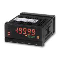
4.2 K3HB-V Initial Setup Example (K3HB-VLC)
The initial setup is explained in the following example.
Settings Example
Indicated as 0 to 1N in the load cell specifications (rated load 1N,
recommended applied voltage 10 V, rated output 2 mV/V *)
• If the measurement value goes above 0.700, comparative output
H turns ON.
• If the measurement value goes below 0.500, comparative output L
turns ON.
* 2 mV/V indicates a load cell output of 2 mV for 1 V applied voltage
for the rated load (when using a load of 1 N). When the applied
voltage is 10 V, the load cell output is 20 mV (2 mV
×10)
Initial Setup Flow
● Note ●
To change a set value, press the S [SHIFT] Key. (The digit that can be
changed will flash.) Use the S [SHIFT] Key to move to the digit to be
changed, and change the setting using the U [UP] Key.
• If the display flashes “
s. err” this indicates that the input is outside
the set range, and does not indicate product failure.
● Note ●
1. Move to the initial setting level by pressing the L [LEVEL] Key for at least
3 s (operation will stop).
2. Set input type A “in-ta” to “b lc” and press the
M [MODE] Key twice.
+10V
−
−IN
+IN
0V
OUT
−OUT
BE
+
Load cell
0.500
0.700
0.000 mV
19.999 mV
1.000
0.000
Display value
Input
value
Comparative output H
Comparative output L
Measurement
value
When the power is turned ON,
a number may be displayed that
is unrelated to the input range
setting.
To display correct values, the
correct input type must be
selected for the wiring.
A Check the wiring and turn the power ON.
Do not change the order of step
B.
When input type A is set, the
scaling value and decimal point
position will be initialized
automatically.
B Set input type A to 0.000 to 19.999 mV.
 Loading...