Appendices
Sampling and comparative output response times
A-15
■
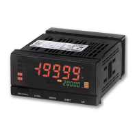
Output response time
The comparative output response time is the sum of the data
processing time and the output (relay or transistor) response time.
(Note 1.)
For transistor outputs
For one input: OFF → ON 1 ms and ON → OFF 1.5 ms
For two inputs: OFF → ON 2 ms and ON → OFF 2.5 ms
For relay outputs
The relay operation time of 10 ms is added to the transistor output
response times.
■
Operation timing examples
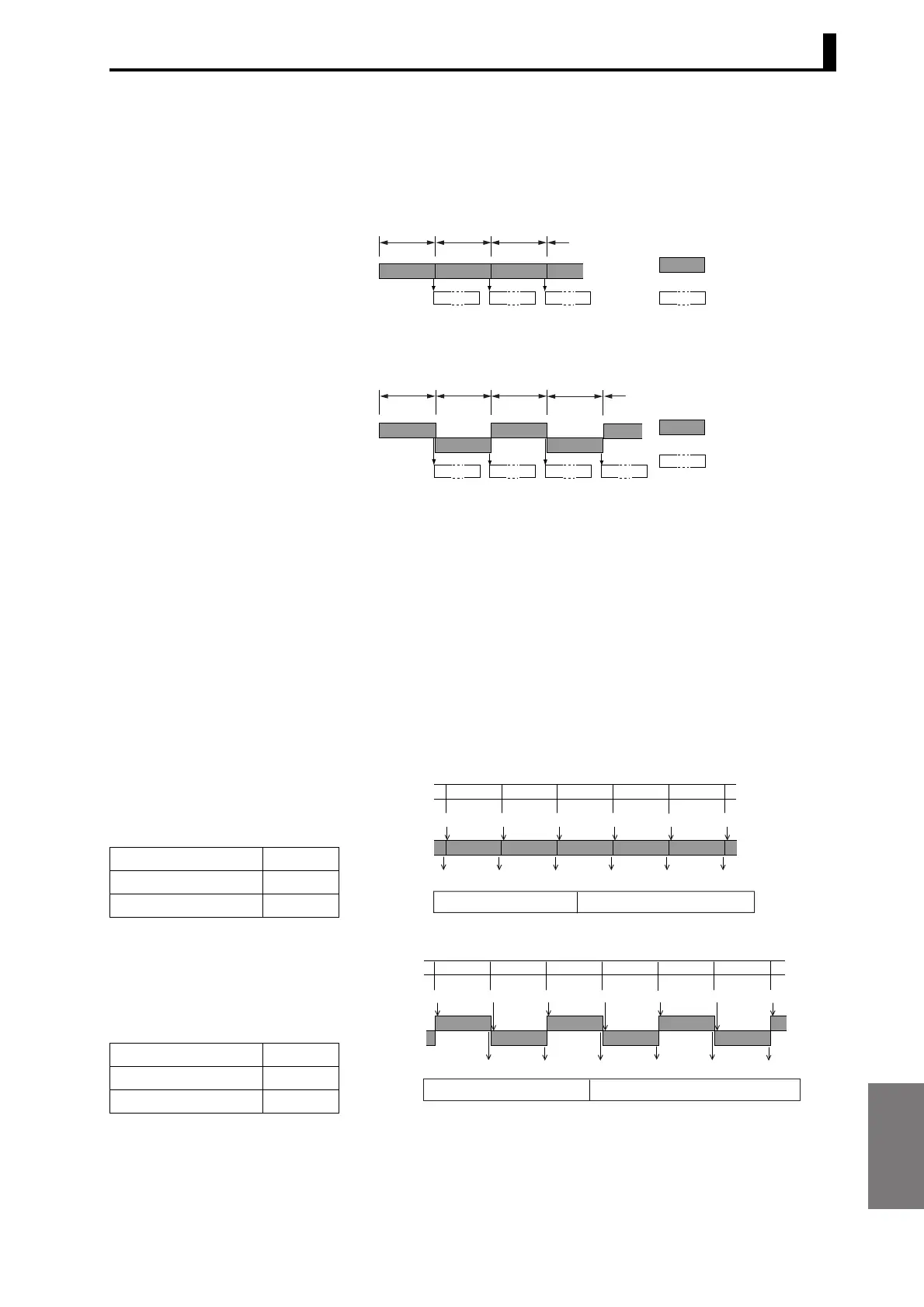
Example 1
The Unit operates as shown
in the diagram to the right
for the settings shown in the
table below.
Example 2
The Unit operates as shown
in the diagram to the right
for the settings shown in the
table below.
0.5 ms 0.5 ms 0.5 ms
Output response
time (See note 1.)
● Two inputs
● One input
Data processing
time
0.5 ms 0.5 ms 0.5 ms 0.5 ms
R
R R RR
R R R
Output response
time (See note 1.)
Data processing
time
R
Calculation A
Timing hold mode Normal
Averaging times (n) Once
Input
Input
Input
Input
Input
Comparative output response time
0.5 ms + output response time (See note 1.)
0.5
Output Output
Output
Output
Output
Input
Output
0.5 0.5
0.5 0.5
Calculation A+B
Timing hold mode Normal
Averaging times (n) Once
Input A
Input B
Input
InputInput
Input
Input
Output Output Output
Output
Output
Output
Input
Input
0.5 0.5 0.5 0.5 0.5 0.5
* The output every 0.5 ms is the comparative output corresponding
to the input change for either input A or input B. The input change
for both inputs is reflected in the comparative outputs every 1 ms.
Comparative output response time
0.5 ms + output response time (See note 1.)

 Loading...