Functions and Operations
5.2 Setting Input Types
5-11
5.2 Setting Input Types
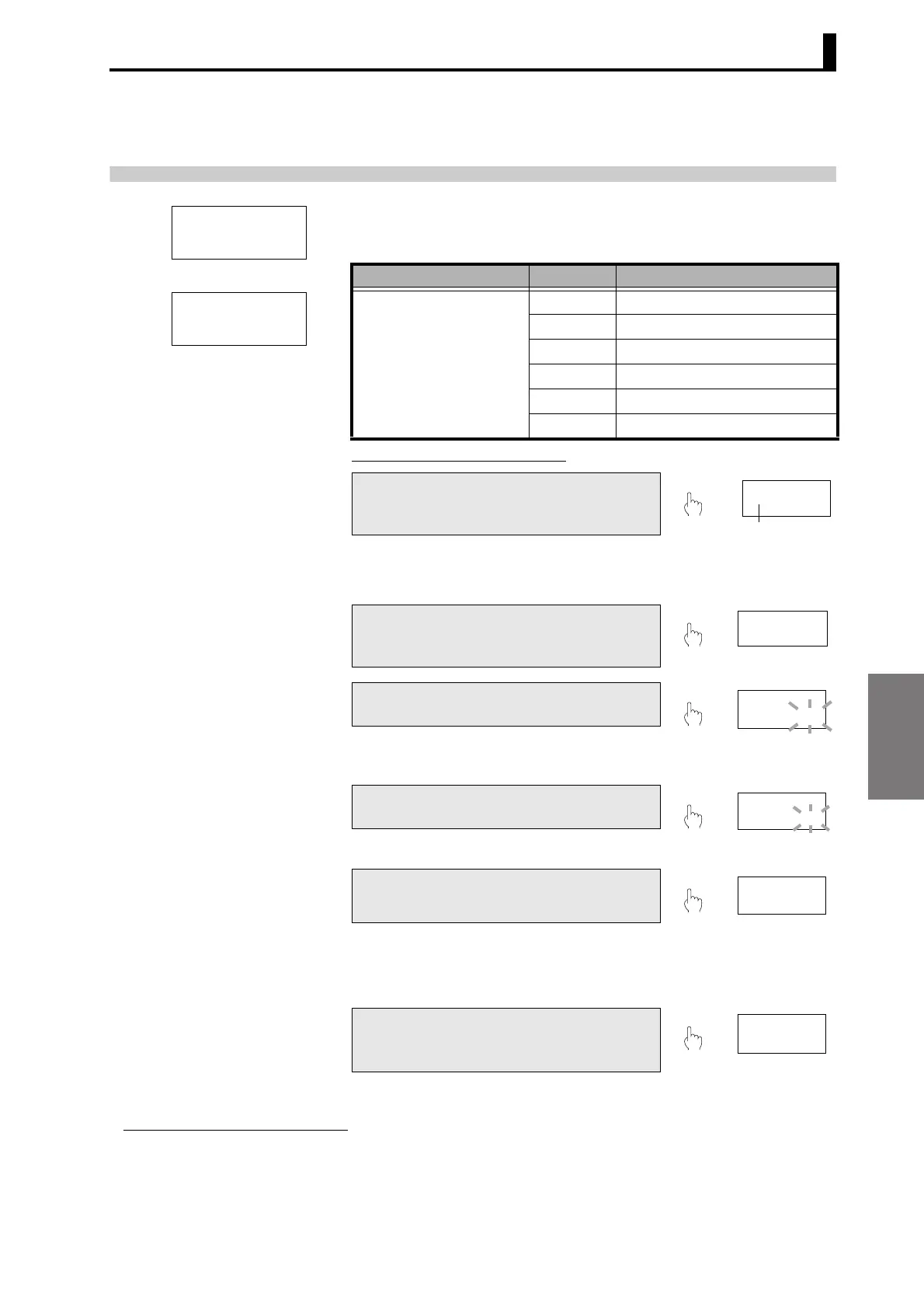
Set the input types at the next parameter to match the connected input
devices. Set input type A to match the device connected to input A and
set input type B to match the device connected to input B.
Parameter Setting Procedure
Important *
Initial setting level
Parameter Set value Meaning of set value
Input type A
in-ta
or
Input type B
in-tb
0-20 0 to 20 mA
4-20 4 to 20 mA
0-5 0 to 5 V
1-5 1 to 5 V
5 ±5 V
10 ±10 V
A Press the L[LEVEL] Key for at least 3
s in RUN level to move to the initial
setting level.
3 s min.
•"
L
0" is displayed on the level/bank
display to indicate the initial setting
level.
B If the PV display is not "in-ta" or "in-
tb", press the M[MODE] Key to
display the desired parameter.
C Press the S[SHIFT] Key to make the
SV display flash.
• The setting can be changed when the
SV display starts to flash.
D Use the U[UP] Key to change the set
value.
E Press the M[MODE] Key to switch to
the next parameter.
• The set value is registered. * The display may
differ.
in-ta
L
0
(IN-TA)
in-tb
L
0
(IN-TB)
L
cal
L
0
Displays "
L
0".
0
M
in-ta
4-20
L
0
S
in-ta
4-20
L
0
U
in-ta
1-5
M
inp. a1
* If input type A is changed, scaling input values A1 and A2 and scaling display values A1 and A2
are initialized. The same applies for input type B.
F Press the L[LEVEL] Key for at least 1
s to return to the RUN level.
1 s min.
L
1234. 5
1234. 5

 Loading...