Preparations
Section 2 Preparations
2-6
■ Wiring
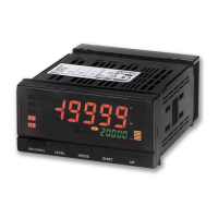
Use the crimp terminals suitable for M3 screws shown below.
● Power supply
Supply power to terminal numbers A1 and A2. The power supply
specifications are outlined below.
100 to 240 VAC, 50/60 Hz, 18 VA max. (at max. load)
24 VAC/VDC, 50/60 Hz, 12 VA max./7 W max. (at max. load.)
(No polarity)
When the power is turned ON, a power supply capacity greater than the
rated power supply is required. When multiple Units are being used,
make sure that the operating power supply has sufficient capacity.
Complying with UL/CSA Standards
Use an SELV power supply with overcurrent protection for the DC
power supply. An SELV power supply has double or reinforced
insulation between the input and output, an output voltage of 30 V rms
and 42.4 V peak, and is 60 VDC or less.
Recommended Power Supply: S8VS-06024@ (from OMRON)
●
Sensor power supply
The sensor power can be supplied from terminals B5 and B6. The
power supply specifications are outlined below.
12 VDC 80 mA
●
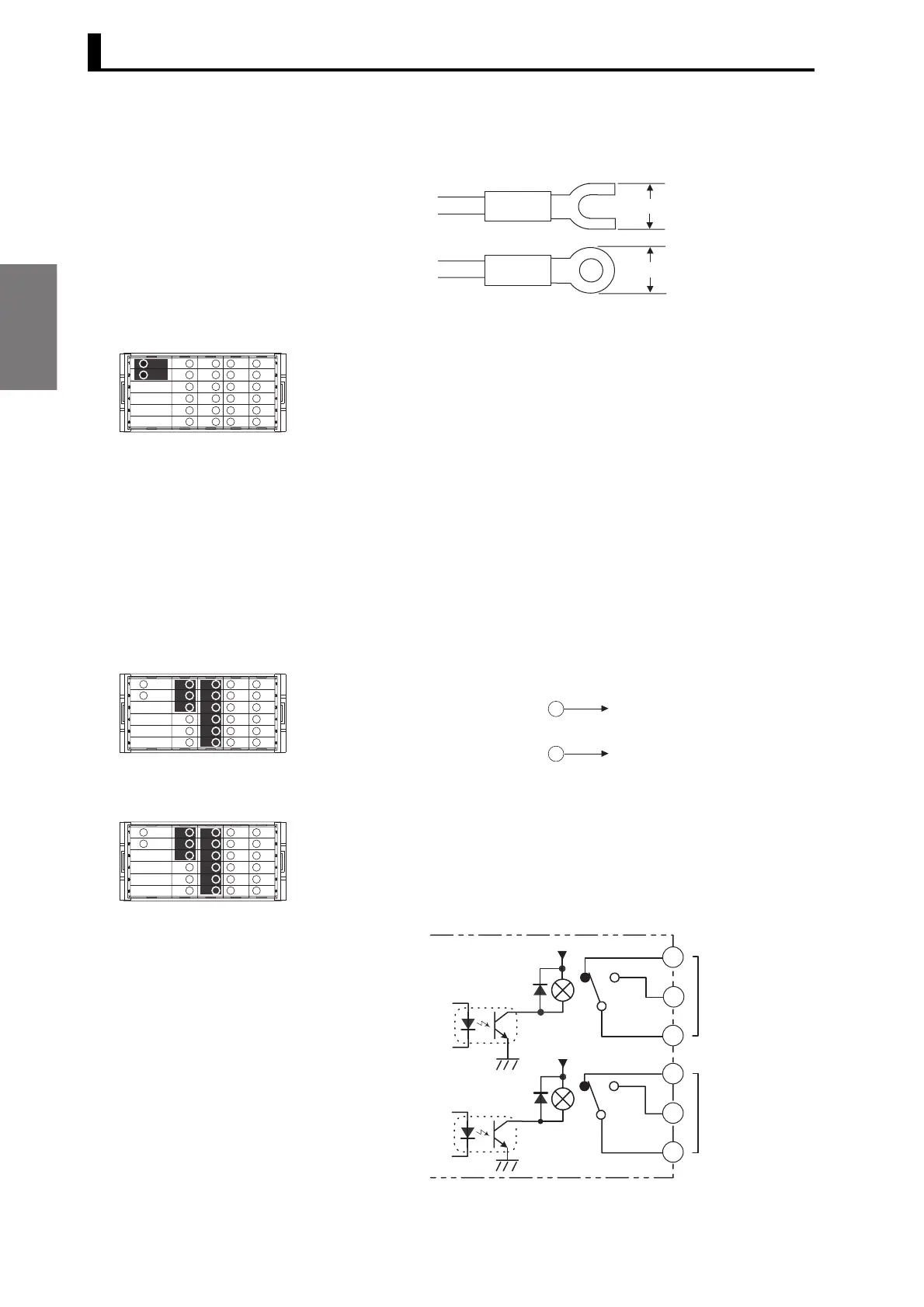
Comparative outputs
Comparative outputs are output to terminals B1 to B3 and C1 to C6.
Connect loads within specifications.
The electrical life expectancy of the relays is 100,000 operations.
Circuit Diagrams
<Contact outputs>
<C1> H and L output model
5.8 mm max.
5.8 mm max.
1
2
3
4
5
6
A
B
C
D
E
1
2
3
4
5
6
A
B
C
D
E
+
-
B5
B6
1
2
3
4
5
6
A
B
C
D
E
H
5 V
5 V
C1
C4
C5
C2
C6
C3
L

 Loading...