Power supply environment
In the following cases, the internal converter module (rectifier) may be damaged.
Take countermeasures such as installing an AC reactor on the main circuit input side of the inver-
ter.
•
The power supply voltage unbalance factor is 3% or more.
• The power supply capacity is at least 10 times larger than the inverter capacity and, at the same
time, 500 kVA or more.
• Rapid change in the power supply voltage occurs.
Example) When the phase advance capacitor is turned ON/OFF, the inverter may detect an over-
voltage or the rectifier may be damaged.
Installing input surge absorber
When using an inductive load (such as a magnetic contactor, magnetic relay, magnetic valve, sole-
noid, or electromagnetic brake), use a surge absorber or diode together.
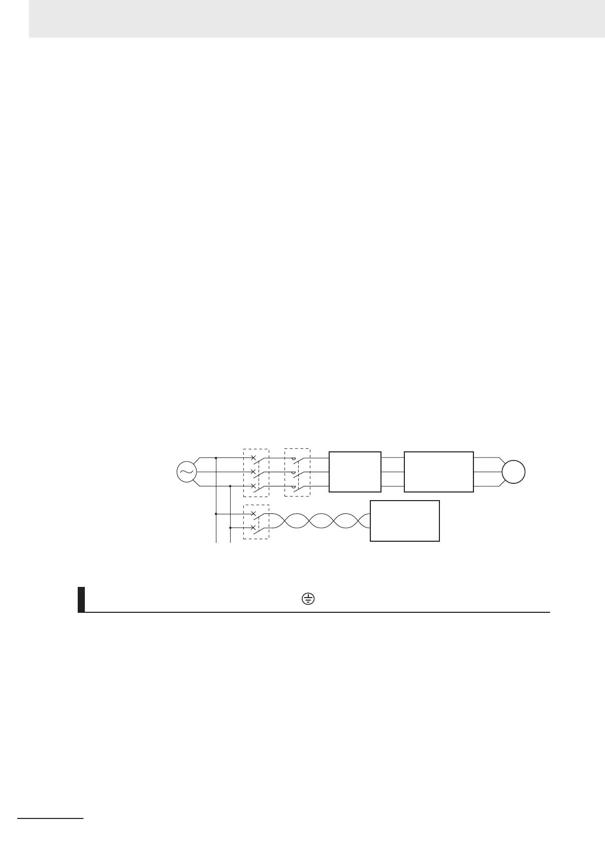
Installing input noise filter
The inverter performs high-speed output switching, which may cause the noise flow from the inver-
ter to power supply lines that negatively affects on peripheral equipment.
Therefore, it is recommended to use an input noise filter to reduce noise flowing out to power sup-
ply lines.
This also helps reduce noise that enters the inverter from power supply lines.
M
MC
MCCB
Input noise filter for inverter (for general use)
Inverter
Other control equipment
3G3M1 Series
CS/CJ Series
Noise filter
Three-phase 200 VAC
Three-phase 400 VAC
Power
supply
Wiring for Ground Terminal (G )
To prevent electric shock, be sure to ground the inverter and the motor.
The 200-V class should be connected to the ground terminal under type-D grounding conditions (con-
ventional type 3 grounding conditions: 100 Ω or less ground resistance), the 400-V class should be
connected to the ground terminal under type-C grounding conditions (conventional special type 3
grounding conditions: 10
Ω or less ground resistance).
For the ground cable, use the applicable cable or a cable with a larger diameter. Make the cable
length as short as possible.
When several inverters are connected, the ground cable must not be connected across several inver-
ters or looped. Otherwise, the inverters and peripheral control equipment may malfunction.
2 Design
2-44
M1 Series Standard Type User's Manual (I669)
 Loading...


