• If you use a general earth leakage breaker (which detects high-frequency leakage current), se-
lect one with a sensitivity current rating of 200 mA or higher per inverter and an operation time of
0.1 s or longer.
Leakage current from EMC noise filter
The EMC noise filter is designed to comply with European CE standards.
Specifically, it is designed to meet the neutral-point grounding requirement of the European power
supply specifications. Therefore, using the EMC noise filter with the phase S grounding causes an
increase of leakage current.
For use with the phase S grounding, it is recommended to use the Input Noise Filter.
•
OMRON currently plans to support the EMC noise filters for the 3G3M1 Series.
Installing magnetic contactor
To shut off the main circuit power supply with a sequence, you can use a magnetic contactor (MC)
on the inverter side closer than a molded case circuit breaker (MCCB).
• Do not attempt to run/stop the inverter by turning ON/OFF a magnetic contactor.
Instead, use the RUN command signal (FW/RV) via the control circuit terminal block of the inver-
ter.
• Construct a sequence that turns OFF the power supply via the alarm output signal of the inverter.
• To use one or more braking resistors/regenerative braking units, construct a sequence that turns
OFF a magnetic contactor via a thermal relay contact in each unit.
Inrush current flow when the inverter power supply is turned ON
When the inverter power supply is turned ON, the charging current, which is called inrush current,
flows in the main circuit board capacitor.
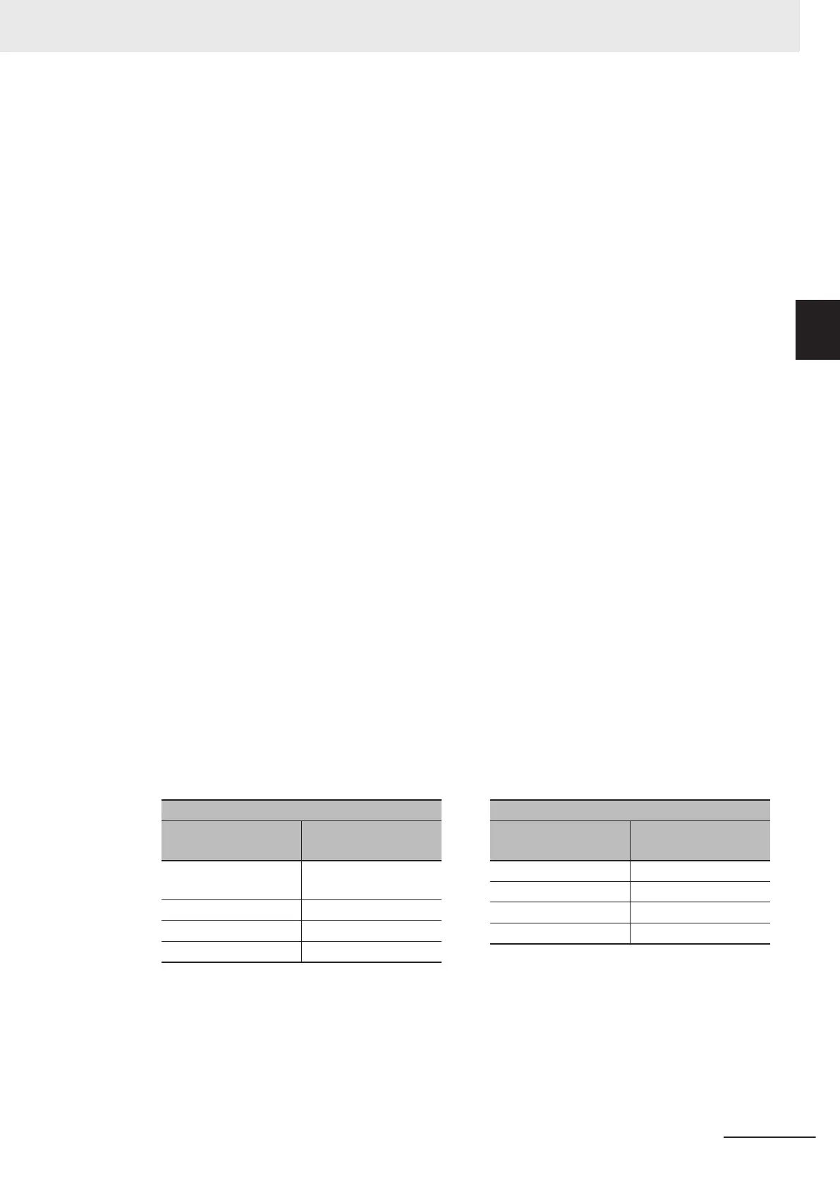
The table below shows the reference values at a power supply voltage of 200 V or 400 V when the
power supply impedance is low. Take this into consideration when selecting the inverter power sup-
ply.
• With a low-speed no-fuse breaker, an inrush current 10 times the rated current can flow for 20
ms.
• To turn ON the power supply for multiple inverters simultaneously, select a no-fuse breaker
whose 20-ms allowable current rating is greater than the total inrush current of the inverters.
Single-phase/Three-phase 200-V class
3G3M1-□
Inrush current value
(Ao-p)
A2001 to A2037
AB001 to AB022
12
A2055, A2075, AB037 126
A2110, A2150 251
A2185 145
Three-phase 400-V class
3G3M1-□
Inrush current value
(Ao-p)
A4004 to A4040 13
A4055, A4075 41
A4110, A4150 81
A4185, A4220 148
Main power supply phase loss and single-phase input
To use a single-phase power supply, use a single-phase 200-V class inverter.
Using a single-phase power supply to supply power to a three-phase 200-V or three-phase 400-V
class inverter may cause damage to the inverter.
Be sure to check that the three-phase power supply is wired properly before using the inverter.
2 Design
2-43
M1 Series Standard Type User's Manual (I669)
2-3 Wiring
2
2-3-4 Wiring for Main Circuit Terminals
 Loading...


