Wiring for Main Power Supply Input Terminals (L1/R, L2/S, L3/T)
The following describes the wiring for the main power supply input terminals and for peripheral equip-
ment.
Installing molded case circuit breaker
If the inverter’s protective function is activated, the inverter internal circuit may be damaged de-
pending on the condition.
Be sure to connect the main power supply input terminals (L1/R, L2/S, L3/T) to the power supply
via a molded case circuit breaker (MCCB) according to each inverter.
• When using multiple inverters, install one MCCB per inverter
.
• Determine the capacity of the MCCB according to the molded case circuit breaker (MCCB) value
shown in the previous table.
• Determine the time characteristic of the MCCB upon due consideration of the time characteristic
of the inverter’s overheat protection function (150% of the rated output current for one minute).
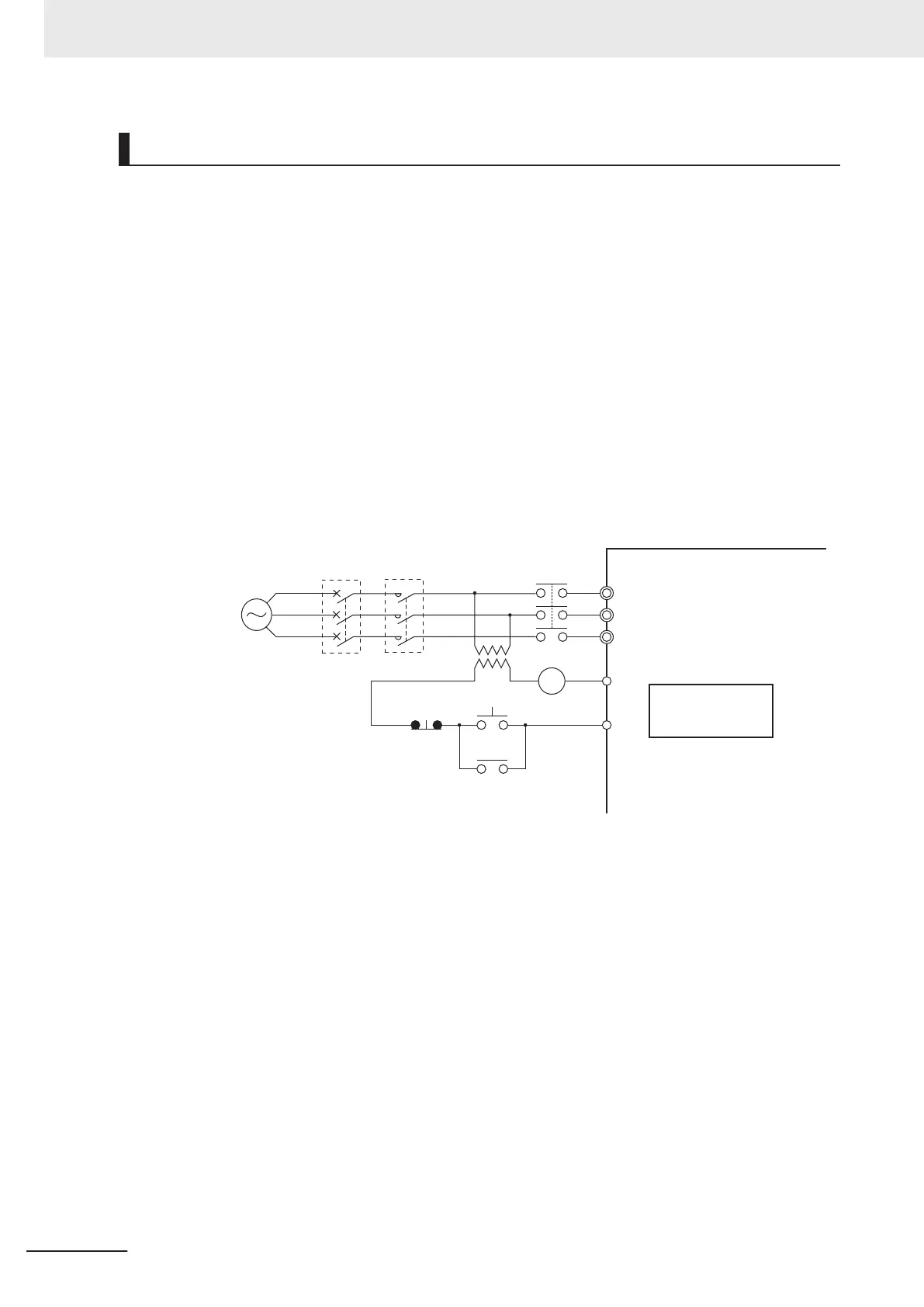
• If you must share one MCCB with multiple inverters or other equipment, construct a sequence
that turns OFF the power supply via the alarm output signal, as shown in the figure below.
L1/R
L2/S
L3/T
ROB
ROC
X
X
X
ONOFF
MC
MCCB
Three-phase 200 VAC
Three-phase 400 VAC
Power
supply
Inverter
Alarm signal
*2
(NC contact)
*1
*1. For 400-V class, connect a 400/200-V transformer.
*2. Set the Output Terminal [ROA, ROB] Function Selection (E27) to “1099: AL (Alarm signal).”
Installing earth leakage breaker
When selecting the earth leakage breaker to use between the power supply and the main power
supply input terminals (L1/R, L2/S, L3/T), consider the following.
High-frequency leakage current from inverter
The inverter produces a high-frequency leakage current due to its high-speed output switching.
In general, a leakage current of approx. 100 mA will flow for the power cable length of 1 m per in-
verter
. Moreover
, an additional leakage current of approx. 5 mA will flow with the increasing length
by 1 m.
Therefore, an earth leakage breaker to use in the power input section must be dedicated for the
inverter
, which removes high-frequency leakage current and detects only the leakage current in a
frequency range that is dangerous to the human body.
• Select a special earth leakage breaker for the inverter with a sensitivity current rating of 10 mA or
higher per inverter.
2 Design
2-42
M1 Series Standard Type User's Manual (I669)
 Loading...


