Note 3:
When the recommended wire size is 60 mm
2
, use crimped terminal model No. 60-6 made by
J.S.T. Mfg. Co., Ltd. or an equivalent product (*2 in table).
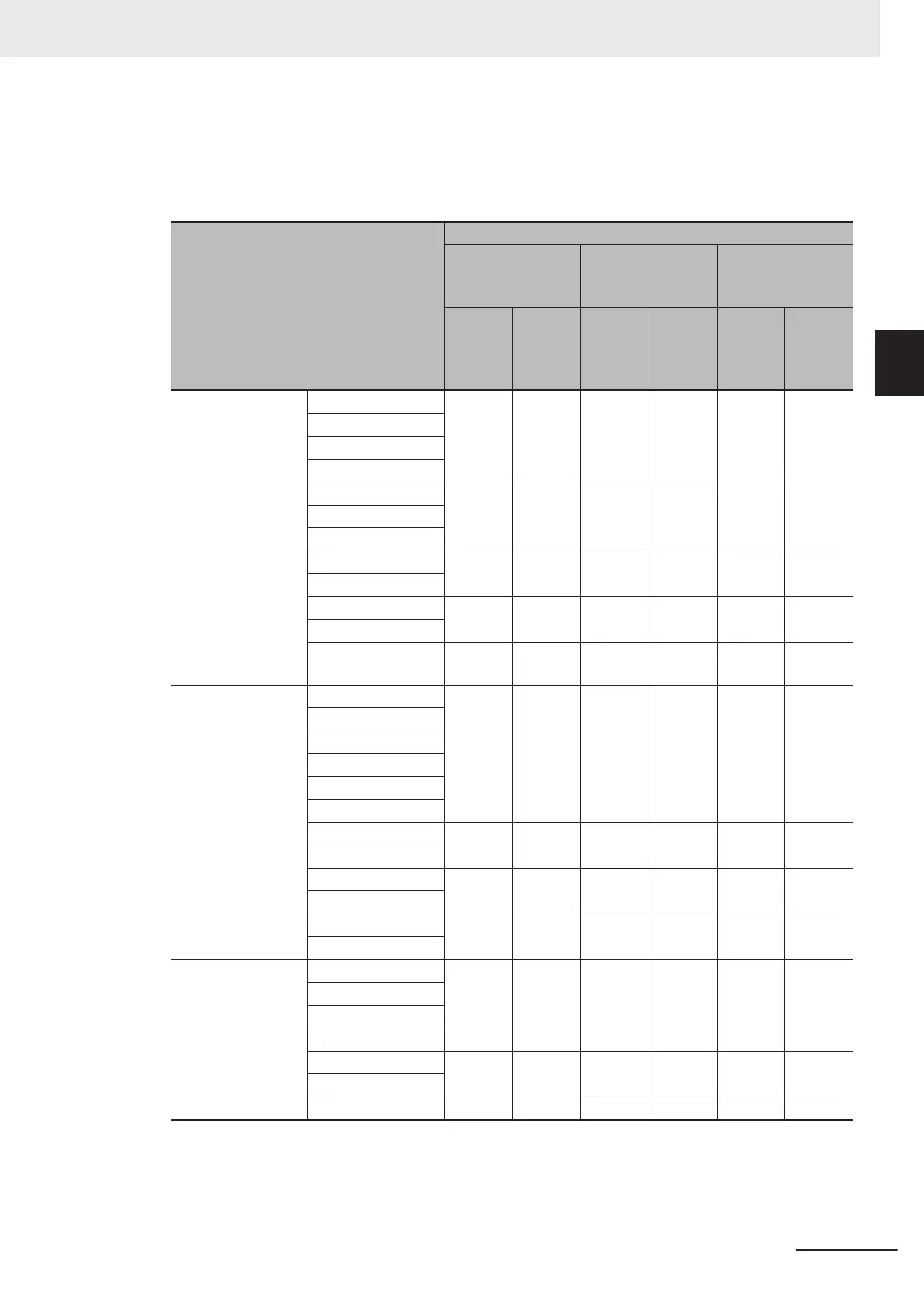
Tightening torque
Model
Screw specification
Main circuit For ground
Control power
supply auxiliary
input (R0, T0)
Termi-
nal
screw
size
Tighten-
ing tor-
que
[N·m]
Termi-
nal
screw
size
Tighten-
ing tor-
que
[N·m]
Termi-
nal
screw
size
Tighten-
ing tor-
que
[N·m]
Three-phase 200 V 3G3M1-A2001 M3.5 0.8 M3.5 1.2 - -
3G3M1-A2002
3G3M1-A2004
3G3M1-A2007
3G3M1-A2015 M4 1.2 M4 1.8 - -
3G3M1-A2022
3G3M1-A2037
3G3M1-A2055 M5 3 M5 3 - -
3G3M1-A2075
3G3M1-A2110 M6 3 M6 3 - -
3G3M1-A2150
3G3M1-A2185 M6 (No.
3)
5.8 M6 (No.
3)
5.8 M3.5 1.2
Three-phase 400 V 3G3M1-A4004 M4 1.2 M4 1.8 - -
3G3M1-A4007
3G3M1-A4015
3G3M1-A4022
3G3M1-A4030
3G3M1-A4040
3G3M1-A4055 M5 3 M5 3 - -
3G3M1-A4075
3G3M1-A4110 M6 3 M6 3 - -
3G3M1-A4150
3G3M1-A4185 M6 (No.
3)
5.8 M6 (No.
3)
5.8 M3.5 1.2
3G3M1-A4220
Single-phase 200 V 3G3M1-AB001 M3.5 0.8 M3.5 1.2 - -
3G3M1-AB002
3G3M1-AB004
3G3M1-AB007
3G3M1-AB015 M4 1.2 M4 1.8 - -
3G3M1-AB022
3G3M1-AB037 M5 3 M5 3 - -
2 Design
2-41
M1 Series Standard Type User's Manual (I669)
2-3 Wiring
2
2-3-4 Wiring for Main Circuit Terminals
 Loading...


