• The power supply and voltage (SELV) with reinforced or double insulation should be used for wir-
ing to the control circuit terminals.
• To satisfy electrical safety requirements, the inverter must be protected with fuses or a molded
case circuit breaker (MCCB) in case a short-circuiting accident occurs. Be sure to install fuses or
a molded case circuit breaker (MCCB) on the power supply side of the inverter
.
The fuses, if used, should be one of the UL-compliant Class-J product listed in 2-4-3 UL/cUL
Standards Cautions on page 2-76.
• Use one molded case circuit breaker (MCCB), or one set of fuses, per inverter.
• Use the crimp terminal with an insulation sleeve to connect to the main circuit terminals.
Compliance with EU Low Voltage Directive
• Be sure to ground the ground terminal
G. Do not use only an earth leakage circuit
breaker* (RCD: Residual-current-operated protective device/ELCB: Earth Leakage Circuit
Breaker) as protection against electric shock. Also, use ground cable of the size of the
power line or larger diameter.
*With overcurrent protection function
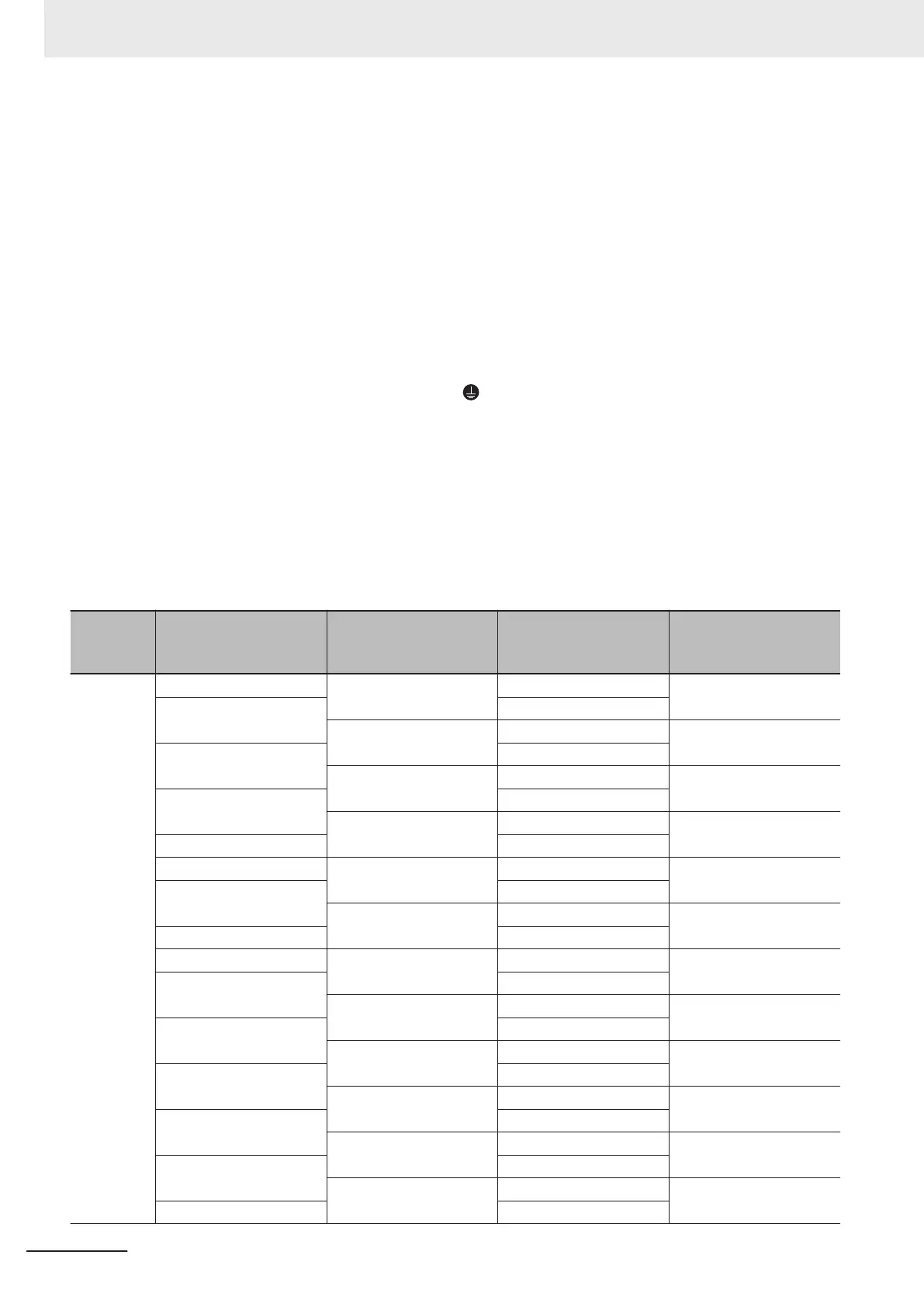
• T
o protect against high voltage that accompanies inverter damage and the risk of acci-
dents, install a fuse having the rating specified in the table below on the power supply
side.
• Breaking capacity 10 kA or more, rated voltage 500 V or less
Power
supply
line
Standard applicable
motor (kW)
Inverter model Specifications Fuse rating (A)
Three-
phase 200
V
0.1 3G3M1-A2001 HHD 50 (IEC 60269-4)
0.2 HND
3G3M1-A2002 HHD 50 (IEC 60269-4)
0.4 HND
3G3M1-A2004 HHD 50 (IEC 60269-4)
0.75 HND
3G3M1-A2007 HHD 50 (IEC 60269-4)
1.1 HND
1.5 3G3M1-A2015 HHD 80 (IEC 60269-4)
2.2 HND
3G3M1-A2022 HHD 125 (IEC 60269-4)
3 HND
3.7 3G3M1-A2037 HHD 125 (IEC 60269-4)
5.5 HND
3G3M1-A2055 HHD 160 (IEC 60269-4)
7.5 HND
3G3M1-A2075 HHD 200 (IEC 60269-4)
11 HND
3G3M1-A2110 HHD 200 (IEC 60269-4)
15 HND
3G3M1-A2150 HHD 250 (IEC 60269-4)
18.5 HND
3G3M1-A2185 HHD 250 (IEC 60269-4)
22 HND
2 Design
2-64
M1 Series Standard Type User's Manual (I669)
 Loading...


