Power supply line
Standard applicable motor (kW)
Inverter model
Specifications
Molded
case circuit
breaker
(MCCB) or
earth leak-
age circuit
breaker
(RCD/ELCB)
rated cur-
rent
*1
Recommended wire size (mm
2
)
For main circuit
For control circuit terminal
Control power supply auxiliary input R0, T0
Main power
supply input
[L1/R, L2/S,
L3/T]
*2
Inverter
ground
[
]
*2*3
Inverter output [U, V, W]
*2
For DC reactor connection [P1, P(+)]
For braking resistor connection [P(+), DB]
*2
With DC reactor
Without DC reactor
With DC reactor
Without DC reactor
With DC reactor
Without DC reactor
Sin-
gle-
phas
e
200
V
0.1 3G3M1-
AB001
HHD 5 5 2.5 2.5 2.5 2.5 2.5 2.5 2.5 0.75 -
0.2 HND
3G3M1-
AB002
HHD
0.4 HND 10
3G3M1-
AB004
HHD
0.55 HND 10
0.75 3G3M1-
AB007
HHD 15
1.1 HND 15 20
1.5 3G3M1-
AB015
HHD
2.2 HND 30 30 4 4 4
3G3M1-
AB022
HHD 20
3.0 HND 30 40 4 4 6
3.7 3G3M1-
AB037
HHD 40 60 6 10 6 10 10
*1. The frame size and model of MCCB, RCD or ELCB (with overcurrent protection function) change according to the ca-
pacity of the power transformer
. For details on selection method, refer to related technical data.
*2.
The recommended size of wire to the main circuit terminal is the size when PVC wire having an allowable temperature
of 70°C and a rated voltage of 600 V is used, and the ambient temperature is 40°C.
*3.
Only one wire of recommended size can be connected to the ground terminal.
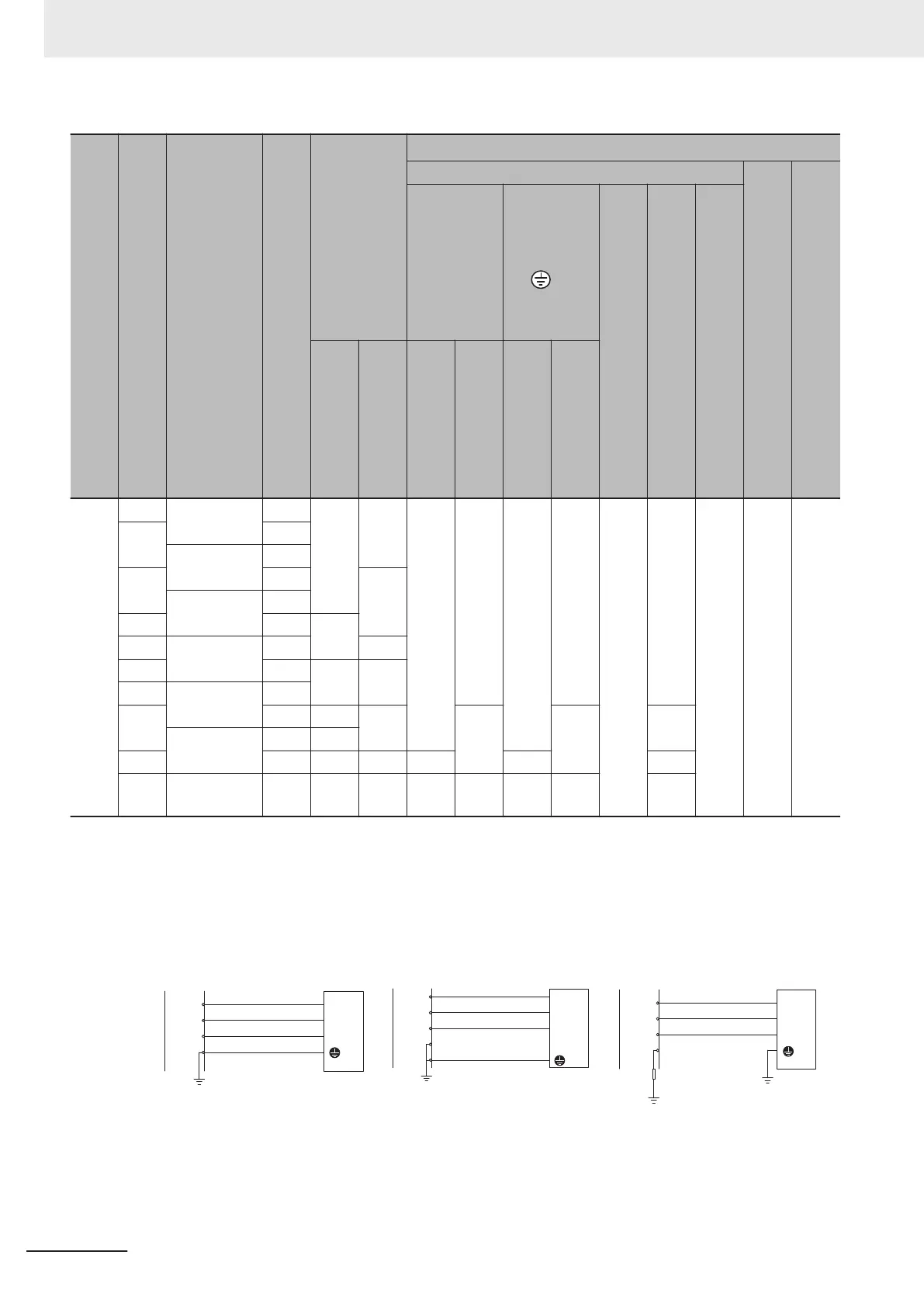
• Use this product on the following power supply system.
L1
L2
L3
PEN
L1/R
L2/S
L3/T
G
Inverter
TN-C system
Power supply
Inverter
Power supply
L1
L2
L3
N
L1/R
L2/S
L3/T
TN-S system
PE
G
Inverter
Power supply
L1
L2
L3
N
L1/R
L2/S
L3/T
IT system
*1
G
2 Design
2-74
M1 Series Standard Type User's Manual (I669)

 Loading...


