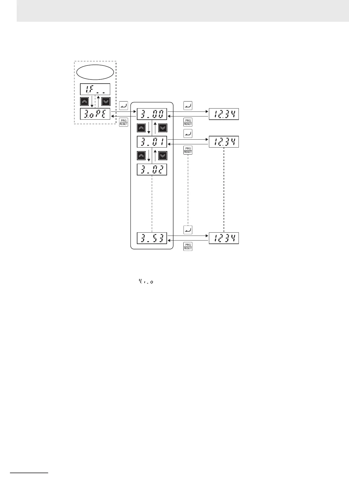
The following figure shows transition through “Operation monitor.”
Program
Mode
Monitor item list Operation information data
Output frequency 1
Output frequency 2
Recovery (follow-up) side
Z-phase pulse rate
I/O check
When menu No. 4 “I/O check:
” is used, the I/O signal status of external signals can be dis-
played on the LED monitor without the need to use a measuring instrument. External signals that
can be displayed are digital I/O signals and analog I/O signals.
For details on “I/O check” display items, refer to 7-1-2 I/O check on page 7-11
.
The following figure shows transition through “I/O check.”
3 Operation and Test Run
3-10
M1 Series Standard Type User's Manual (I669)
 Loading...


