Name Display status
Data display
During a stop, the set frequency (flashes), and during a run, the
output frequency (lit)
RUN command LED indicator Lit when Operator is selected at F02
If any problem is found, the display status will be as follows.
Refer to Sec
tion 9 Troubleshooting on page 9-1for countermeasures.
Name Display status
RUN LED Not lit
ERR LED Lit
PRG LED Not lit
x10 LED Not lit
Hz LED Lit
A LED Not lit
Data display Fault code (high-speed flashing)
RUN command LED indicator Lit when Operator is selected at F02
Parameter Initialization
The set values of parameters can be initialized and returned to their factory default settings. The fault
monitor can also be cleared.
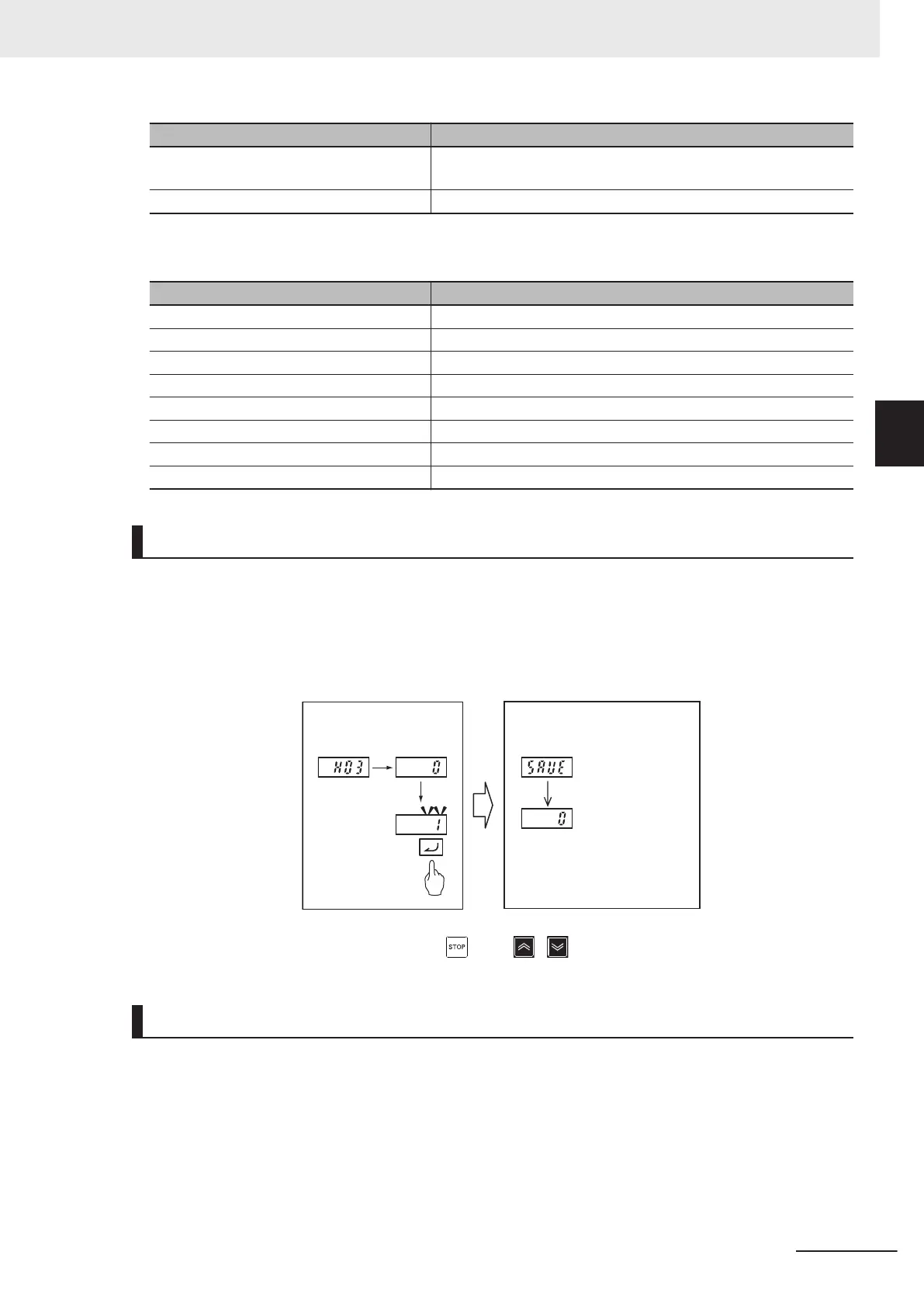
The following figure shows the steps of parameter initialization.
Initialization is executed when “1: Initialize all parameters” is set at Data Initialization (H03).
For details on parameter initialization, refer to 5-1 Display and Initialization on page 5-3.
Step1:Press the Enter
key to set {H03}
to “1.”
Step2:
Initialization is completed
when the “SAVE” display
disappears.
Initializing
Initialization
completed
*1
*1. The Operator displays
the following parameters.
To change the data of parameter H03, the “ key + / keys” must be pressed simultaneously.
Parameter Setting
To operate the inverter, two commands are required: the RUN command and the frequency reference.
Set 1st RUN Command Selection (F02) and 1st Frequency Reference Selection (F01). For the test
run, set 1st Frequency Reference Selection (F01) to “0” and 1st RUN Command Selection (F02) to “2”
so as to operate the inverter via the Digital Operator.
Next, set the 1st Motor Pole Number (P01) and 1st Motor Capacity (P02) for of applicable motor.
These values will be used as the reference values for the automatic torque boost, motor protection
and torque limit functions. Refer to 5-3-1 Induction Motor Basic Settings on page 5-19, 5-3-2 Base
3 Operation and Test Run
3-19
M1 Series Standard Type User's Manual (I669)
3-4 Operation Items for Test Run
3

 Loading...


