1. Set 1st Frequency Reference Selection (F01).
Set “0: Operator” at 1st Frequency Reference Selection (F01).
2. Set 1st RUN Command Selection (F02).
Set forward rotation (2: Touch panel operation (forward)) or reverse rotation (3: Touch panel op-
eration (reverse)) at 1st RUN Command Selection (F02).
3.
Set the output frequency.
Set the set frequency by the
/ keys with the set frequency “0.00” displayed flashing.
Initially, it is recommended to set a low speed of about 5 Hz for safety.
4.
Press the
key.
The motor starts rotating with the RUN LED lit.
5. Check that there is no problem with the output frequency, motor rotation direction or inverter op-
eration displayed on the Digital Operator.
For the rotation direction of motor, refer to rotation direction (monitor mode: 3_06).
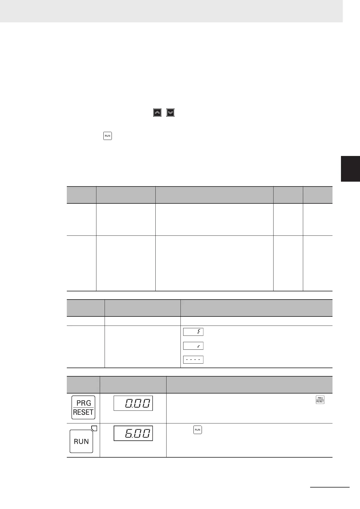
Parame-
ter No.
Function name Set value
Default
data
Unit
C99 1st Frequency Refer-
ence/1st Multi-step
Frequency Reference
0
0.0 to 590.00 Hz 0 Hz
F02 1st RUN Command
Selection
0: Operator (Direction of rotation input: termi-
nal block)
1: External signal (Digital input)
2: Operator (Forward rotation)
3: Operator (Reverse rotation)
4: RS-485 communication
5: Fieldbus (Reserved)
2 -
Monitor
mode
Name Data
3_00 Output frequency 1 0.00 to 99.99 to 590.0 [Hz]
3_06 Rotation direction
: During forward rotation
: During reverse rotation
: During stop
Key opera-
tion
Data display example Description
When the output frequency “0.00” is not displayed, press the
key to display the output frequency.
Press the key. The monitor value of the frequency reference is
displayed on the data display.
3 Operation and Test Run
3-21
M1 Series Standard Type User's Manual (I669)
3-4 Operation Items for Test Run
3

 Loading...


