Parameter
No.
Function name Monitor or Data Range
Default
data
Setting
during
RUN
Unit Page
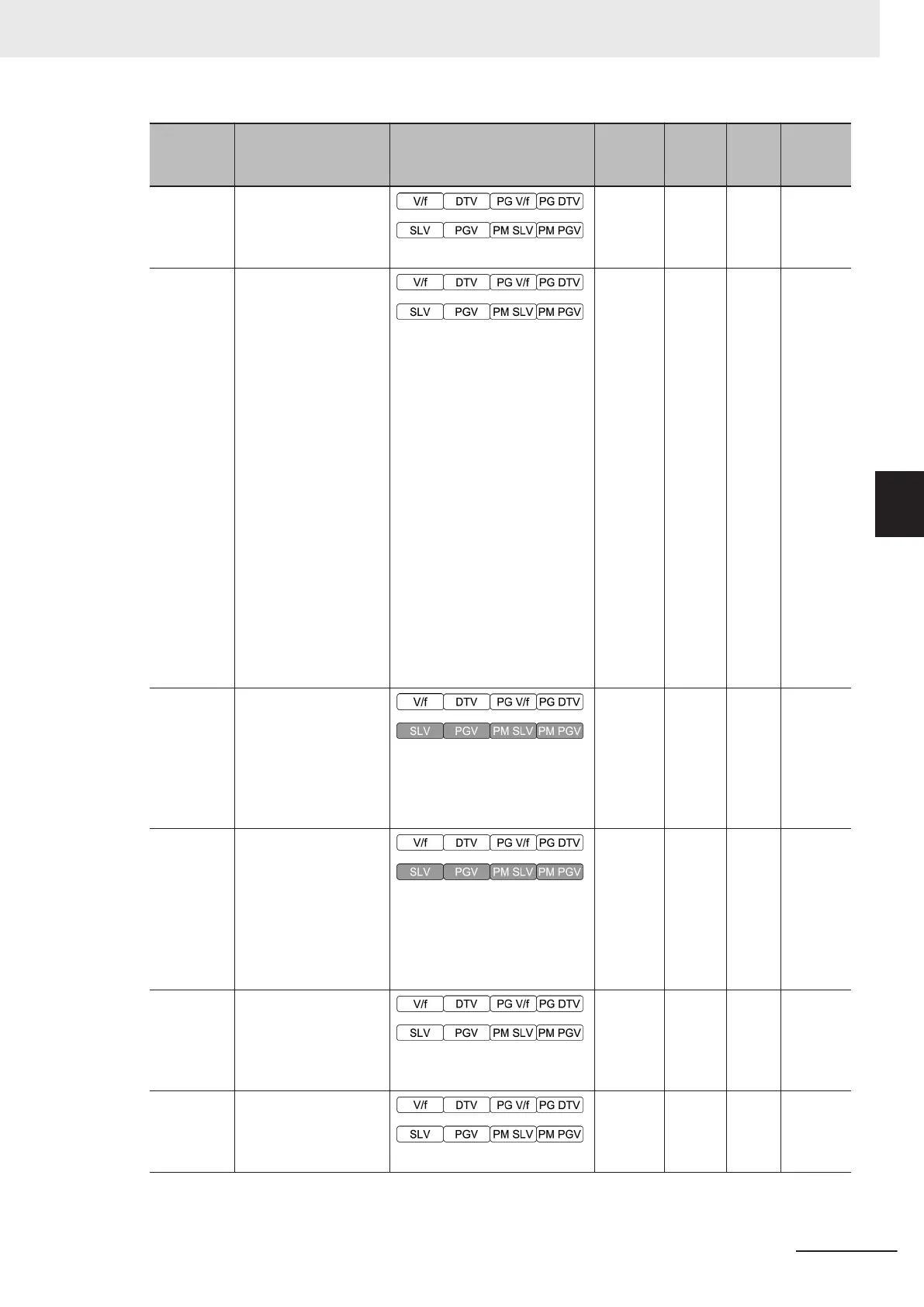
F41 Torque Limit 2
0 to 300 %
300
Availa-
ble
%
page
6-81
F42
1st Drive Control Se-
lection
0 to 16
0 : IM V/f control
1 : IM Dynamic torque vector
control
3 : IM V/f control with speed
sensor
4 : IM Dynamic torque vector
control with speed sensor
5 : IM Vector control without
speed sensor
6 : IM Vector control with
speed sensor
15 : PM Vector control without
speed and pole position sen-
sor
16 : PM Vector control with
speed and pole position sen-
sor
0 - -
page
5-10
page
6-16
page
6-11
page
6-21
F43
1st Overload Protect
Function Selection
0: Disable
1: Enable at constant speed
2: Enable during ACC/
constant speed operation
2
Availa-
ble
-
page
7-82
F44
1st Overload Protect
Level
20 to 200%
100% = Rated output current
of inverter (Default: 180% for
HHD mode and 130% for ND
mode)
180
Availa-
ble
%
page
7-82
F50
Electronic Thermal for
Braking Resistor Dis-
charging Capacity
1 to 9,000 kWs
32,767: Disable
32767
Availa-
ble
kWs
page
5-75
F51
Electronic Thermal for
Braking Resistor Al-
lowable Average Loss
0.001 to 99.99 kW
0.001
Availa-
ble
kW
page
5-75
4 Parameter List
4-83
M1 Series Standard Type User's Manual (I669)
4-2 List of Parameters by Group
4
4-2-1 Parameter F (Basic Functions)

 Loading...


