Parameter
No.
Function name Monitor or Data Range
Default
data
Setting
during
RUN
Unit Page
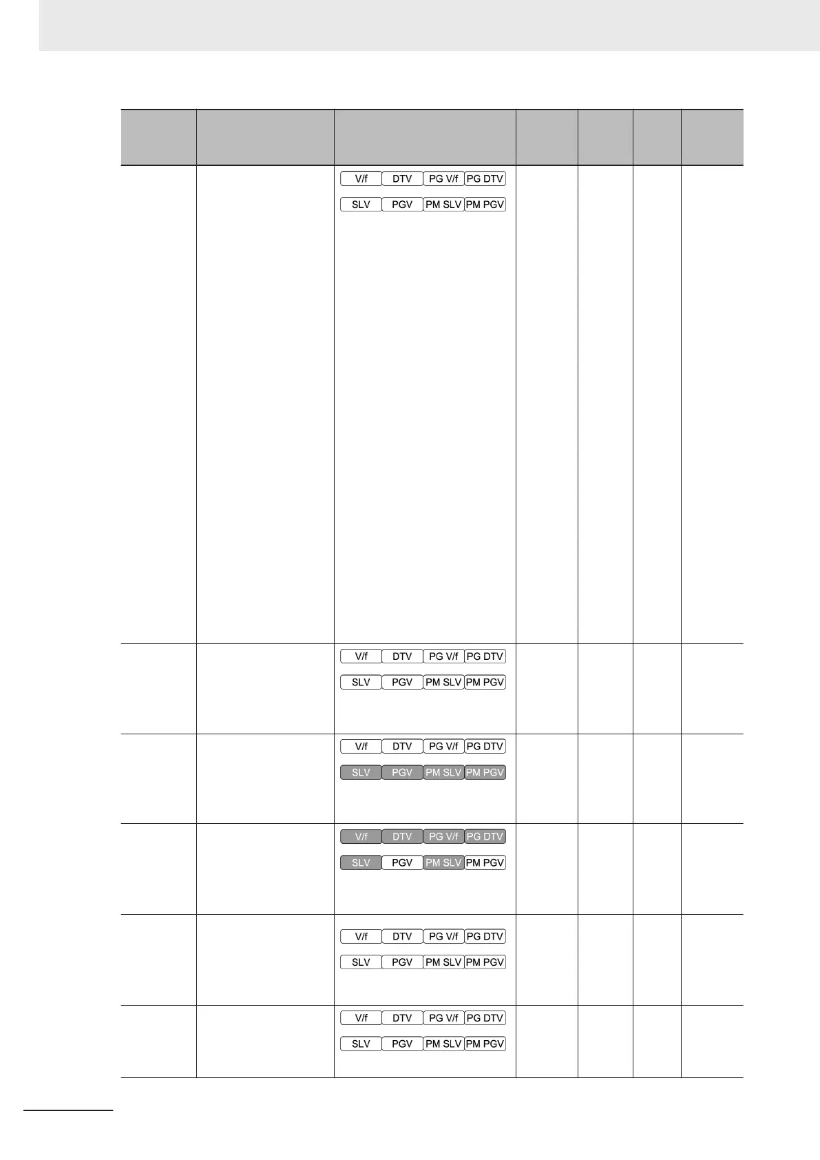
F31
Output Terminal [AO]
Function Selection
0: Output frequency1 (before
slip compensation)
1: Output frequency2 (after
slip compensation)
2: Output current
3: Output voltage
4: Output torque
5: Load ratio
6: Power consumption
7: PID feedback
8: Actual/Estimated speed
9: Main Circuit DC Voltage
10: Communication data AO
13: Motor output
14: Calibration (+)
15: PID command (SV)
16: PID output (MV)
17: Position error in master-
follower operation (Bipolar)
18: Heatsink temperature
21: PG feedback value
27: Thermal load ratio
28: Internal Acc/Dec frequency
29: Output torque (Bipolar)
0
Availa-
ble
-
page
7-46
F33
Output T
erminal [AO]
Pulse Rate (PO)
25 to 32000 p/s
Pulse rate at 100% output
1440
Availa-
ble
p/s
page
7-46
F37
1st V/f Characteristics
Selection
0: Variable torque load
1: Constant torque load
1 - -
page
5-10
F38
1st Overload Early
W
arning Detection
Timer / Low Current
detection level (OL,
LOC)
0: Detected/Estimated speed
1: Reference speed
0 - -
page
7-114
F39
Display Coefficient 1
for Transport Time /
Auxiliary Display Coef-
ficient 1 for Speed
Monitor
0.00 to 10.00 s
0.00
Availa-
ble
s
page
7-114
F40 T
orque Limit 1
0 to 300 %
300
Availa-
ble
%
page
6-81
4 Parameter List
4-82
M1 Series Standard Type User's Manual (I669)

 Loading...


