7-9-2
Automatic Carrier Frequency Reduction
Use this function to reduce the carrier frequency automatically as the output current and the cooling fin
temperature increase.
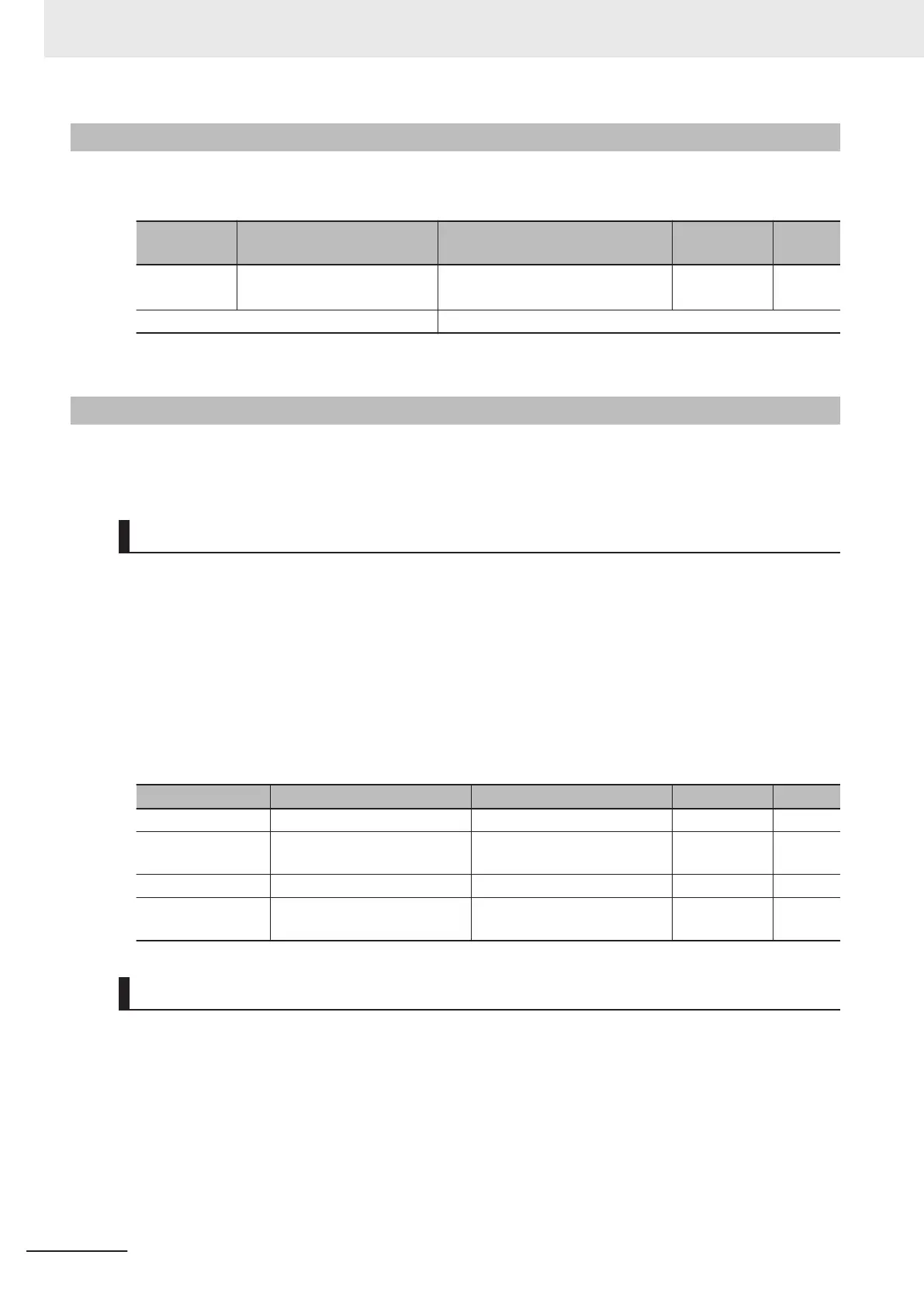
Parameter
No.
Function name Data Default data Unit
E165
Carrier Frequency Automatic
Reduction Function Selection
0: Disable
1 -
1: Enable
Related function F26
• When this function is enabled, overheating or overload trips sometimes can be avoided.
7-9-3
Starting Frequency and Stop Frequency
Set the frequency for starting inverter output when the RUN signal is turned ON, and the frequency for
stopping the inverter output when the RUN signal is turned OFF
.
Starting Frequency
• During V/f control (Drive Control Selection (F42/A14) = 0, 3)
When the inverter operation is started, the output frequency starts from the starting frequency. Set
the starting frequency to enable securing sufficient starting torque. It is also possible to set the Start-
ing Frequency Holding T
ime (F24/A62).
• During vector control (Drive Control Selection (F42/A14) = 1, 4, 5, 6, 15, 16)
When the inverter is started, the speed starts from zero, and acceleration is performed up to the
starting frequency in accordance with the set acceleration time and acceleration pattern. After the
starting frequency holding time has elapsed, acceleration is again performed to the frequency in-
structed in accordance with the acceleration time.
Parameter No. Function name Data Default data Unit
F23 1st Starting Frequency 0.0 to 60.0 0.5 Hz
F24
1st Starting Frequency 1
Holding Time
0.00 to 10.00 0.00 s
A12
2nd Starting Frequency 0.0 to 60.0 0.5 Hz
A62
2nd Starting Frequency Hold-
ing Time
0.00 to 10.00 0.00 s
Stop Frequency
• During V/f control (Drive Control Selection (F42/A14) = 0, 3)
The inverter output is cut of
f at the time the output frequency reaches the stop frequency
.
It is also possible to set the stop frequency (holding time).
•
During vector control (Drive Control Selection (F42/A14) = 1, 4, 5, 6, 15, 16)
The speed detection value/speed estimated value or the speed command reaches the stop frequen-
cy, and the stop frequency holding time elapses, and then inverter output is cut off.
Select the speed detection value/speed estimated value or the speed command at Stop Frequency
Detection Method Selection (F38/A64).
7 Other Functions
7-114
M1 Series Standard Type User's Manual (I669)

 Loading...


