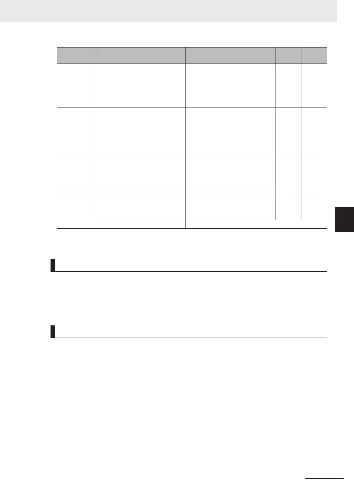
Parameter
No.
Function name Data
Default
data
Unit
F11/A07
1st Motor Electronic Thermal
Level/2nd Motor Electronic Thermal
Level
*1
0.00; 0.01 to 2000
0.00: Disable
0.01 to 2000 A
*Setting range is from 1%(HHD) to
135%(ND) of inverter rated current.
22.5 A
F10/A06
1st Motor Electronic Thermal Char-
acteristic Selection/2nd Motor Elec-
tronic Thermal Characteristic selec-
tion
*1
1 to 2
1: For a general-purpose motor
with shaft-driven cooling fan
2: For an inverter-driven motor non-
ventilated motor or motor with sep-
arately powered cooling fan
1 -
F12/A08
1st Motor Electronic Thermal Time
Constant/2nd Motor Electronic
Thermal T
ime Constant
*1
0.5 to 75.0 5 min
M59
Motor Electronic Thermal Monitor 0.0 to 100.0 0 %
H89
Motor Electronic Thermal Overload
Protection Data Retention
0; 1
0: Disable
1: Enable
0 -
Related function Output terminal functions (OL1, OL2)
*1. To enable switching to the 1st and 2nd control, allocate “12: SET (2nd control)” to either of input terminal
[DI1] to [DI7].
Motor Electronic Thermal Level (F11/A07)
• Set the operation level of the electronic thermal for motor protection. To not use this function, set
0.00.
• Normally, set to the motor continuous allowable current (generally
, about 1.0 to 1.1 times the motor
rated current) when the motor is run at base frequency.
Motor Electronic Thermal Characteristic Selection (F10/A06)
• Select the characteristics of the motor cooling system.
When Motor Electronic Thermal Characteristic Selection (F10/A06) = 1: For
a general-purpose motor with shaft-driven cooling fan
• The figure below shows the electronic thermal operation characteristics. Characterization factors
α1 to α3 and their switching frequencies f2 and f3 differ according to the characteristics of the
motor.
5 Basic Settings
5-21
M1 Series Standard Type User's Manual (I669)
5-3 Motor Parameter Settings
5
5-3-3 Motor Electronic Thermal Function

 Loading...


