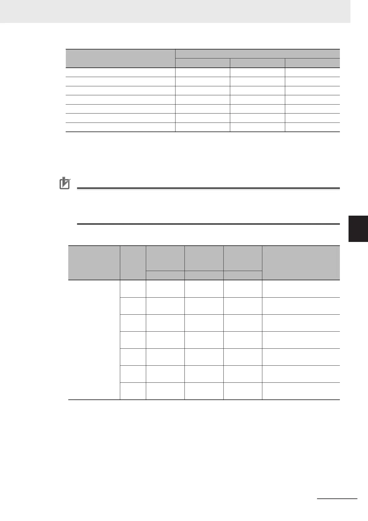
Operation pattern stage No.
Output terminal signal
STG1 STG2 STG4
Stage 1 ON OFF OFF
Stage 2 OFF ON OFF
Stage 3 ON ON OFF
Stage 4 OFF OFF ON
Stage 5 ON OFF ON
Stage 6 OFF ON ON
Stage 7 ON ON ON
• The signal can be output at completion of cycle operation when the pattern operation stage is transi-
tioned to by allocating “16: TU (transition to pattern operation stage)” and “17: T
O (pattern operation
cycle operation completion)” to output terminals DI1 to DI7. For details, refer to the operation exam-
ple figure below
.
Precautions for Correct Use
When C21=0 is set and pattern operation is started by input via the FW/RV terminals turning
ON, the motor stops when the final stage ends even if the FW/R
V terminals stay ON.
At this time, when the value of F01/C30 is changed without turning the FW/RV terminals OFF
,
operation is immediately started according to the set frequency after the value is changed.
Pattern operation setting examples
C21 (Pattern Op-
eration / T
imed
Operation Mode
Selection)
Stage
No.
Operation
time
Rotation di-
rection
Accelera-
tion/deceler-
ation time
Operation (reference) fre-
quency
Set value
Set value
Set value
0
Stage 1 60.0 F 2 C05 Multi-step Frequency
Reference 1
Stage 2 100 F 1 C06 Multi-step Frequency
Reference 2
Stage 3 65.5 r 4 C07 Multi-step Frequency
Reference 3
Stage 4 55.0 r 3 C08 Multi-step Frequency
Reference 4
Stage 5 50.0 F 2 C09 Multi-step Frequency
Reference 5
Stage 6 72.0 F 4 C10 Multi-step Frequency
Reference 6
Stage 7 35.0 F 2 C11 Multi-step Frequency
Reference 7
This is illustrated as follows.
5 Basic Settings
5-37
M1 Series Standard Type User's Manual (I669)
5-5 Frequency Reference
5
5-5-3 Pattern Operation / Timed Operation Function
 Loading...


