0
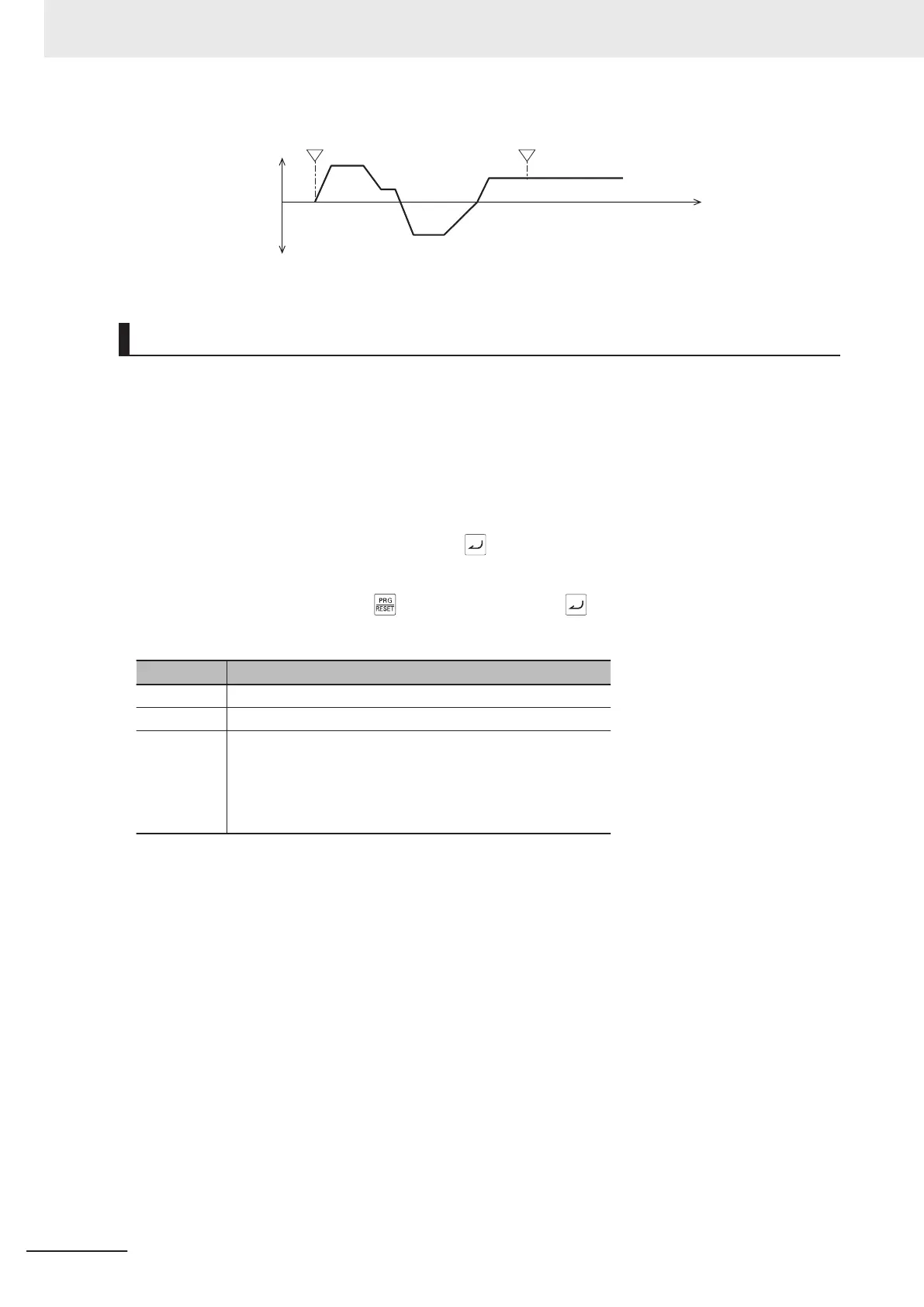
Output frequency
Time
Forward
Reverse
RUN command 1 cycle end
Constant speed operation after 1 cycle operation
Pattern Operation Setting
• To set the patterns in pattern operation, set the operation time, rotation direction and acceleration/
deceleration time to Pattern Operation Stage 1 Operation Setting to Pattern Operation Stage 7 Op-
eration Setting (C22 to C28). The following describes the method for setting stages in Operator and
in Sysmac Studio.
<Setting stages in Operator>
Set the operation time, rotation direction and acceleration/deceleration time of stages 1 to 7 to Pattern
Operation Stage 1 Operation Setting to Pattern Operation Stage 7 Operation Setting (C22 to C28)
For operation on the Digital Operator
, press the key three times for the respective parameter and
set the three types of data.
If parameter setup is exited by the
key before pressing the key three times and setting the
three types of data, the data will not be updated.
Setting Description
First time The operation time is set in the range 0.0 to 6000 s.
Second time The operation direction is to FW (forward) or RV (reverse).
Third time The acceleration/deceleration time is set in the range 1 to 4.
1: Follows F07/F08
2: Follows E10/E1
1
3: Follows E12/E13
4: Follows E14/E15
<Setting stages in Sysmac Studio>
Set Pattern Operation Stage 1 Operation Setting to Pattern Operation Stage 7 Operation Setting (C22
to C28) in hexadecimal.
Example: In case of (reverse rotation, 2nd deceleration time, 10.0 s)
Rotation direction Reverse: 8000 hex
Acceleration/deceleration time 2nd acceleration/deceleration time: 1000 hex
Operation time 10.0 s = 0.1 × 100: 0400 hex + 0064 hex
Accordingly, the set value becomes 8000 hex + 1000 hex + 0400 hex + 0064 hex = 9464 hex
• Stages set with an operation time of 0.0 are disabled and are ignored.
•
Each of Multi-step Frequency Reference 1 to 7 (C05 to C11) is applied to the frequency setting of
stages 1 to 7.
• When “18: STG1 (pattern operation stage No.1)” to “20: STG4 (pattern operation stage No.4)” is al-
located to output terminals DI1 to DI7, the stage (phase of operation) currently operating by ON/OFF
of the output signal can be checked. For details, refer to the operation example figure below.
5 Basic Settings
5-36
M1 Series Standard Type User's Manual (I669)
 Loading...


