Terminal [DO2] Function Selection (E21) and Output Terminal [ROA, ROB] Function Selection
(E27). When the SET terminal is turned ON, 2nd control is selected, and 2nd control under selection
(49: SETM) turns ON.
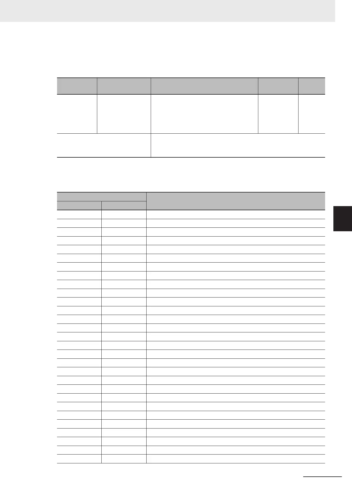
Parameter
No.
Function name Data Default data Unit
E01 to E05,
E98, E99
Input Terminal [DI1]
Function Selection
to Input Terminal
[DI7] Function Se-
lection
12: SET (2nd control selected) - -
Related function Sets “49: SETM (2nd control under selection)” to Output Terminal [DO1]
Function Selection (E20), Output Terminal [DO2] Function Selection
(E21) and Output Terminal [ROA, ROB] Function Selection (E27).
• 1st control and 2nd control cannot be switched when operation is stopped. During operation, the
SET terminal does not operate even if it is turned ON.
The functions that can be switched by the SET terminal are as shown below.
Parameter No.
Parameter name
1st control 2nd control
F042 A014 Drive control selection
F037 A013 V/f characteristics selection
F002 E102 RUN command selection
F001 C030 Frequency Reference Selection
C099 E109 Frequency Reference/Multi-step Frequency Reference 0
F003 A001 Maximum output frequency
F004 A002 Base Frequency
F005 A003 Rated Voltage at Base Frequency
F006 A004 Rated Voltage at Maximum Output Frequency
F007 E010 Acceleration time 1
F008 E011 Deceleration time 1
E012 E014 Acceleration time 2
E013 E015 Deceleration time 2
E125 E128 2-step Acceleration/Deceleration Switching Condition Selection
E127 E126 2-step Acceleration Switching Frequency
E129 E130 2-step Deceleration Frequency
F010 A006 Motor Electronic Thermal Characteristic Selection
F011 A007 Motor Electronic Thermal Level
F012 A008 Motor Electronic Thermal Time Constant
F015 E117 Frequency Upper Limit
F016 E118 Frequency Lower Limit
F020 A009 DC Injection Braking Start Frequency
F021 A010 DC Injection Braking Level
F022 A011 DC Injection Braking Time
F023 A012 Starting frequency
F024 A062 Starting Frequency Holding Time
F025 A063 Stop Frequency
F038 A064 Stop Frequency Detection Method Selection
F039 A065 Stop Frequency Holding Time
5 Basic Settings
5-53
M1 Series Standard Type User's Manual (I669)
5-9 Multi-function Input
5
5-9-1 Input Terminal Functions

 Loading...


